TIDUEA0A March 2019 – September 2020
- Description
- Resources
- Features
- Applications
- 5
- 1System Description
- 2System Overview
-
3Hardware, Software, Testing Requirements, and Test Results
- 3.1 Required Hardware and Software
- 3.2
Testing and Results
- 3.2.1 Test Setup for Performance Testing
- 3.2.2 EMI and EMC Test Requirements for DRTD
- 3.2.3 TMP117 EMI/EMC Test Results
- 3.2.4 TMP117 Based Temperature Probe Measurement Performance Test Results
- 3.2.5 TMP116 Based Temperature Probe Measurement Performance Test Results
- 3.2.6 I2C-bus Cable Length Considerations
- 3.2.7 Power Supply
- 3.2.8 ESD Test Results for TMP116
- 3.2.9 Summary
- 4Design Files
- 5Software Files
- 6Related Documentation
- 7About the Author
- 8Revision History
2.4.1 PT100, PT500, PT1000 based Measurement in Heat Meters
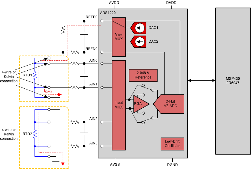
In Figure 2-5 the ADS1220 Delta-Sigma device is used to measure the resistance of two 4-wire PT sensors in series and passes the data to the MSP430 host MCU for conversion from a resistance value to a temperature value, as implemented in the TIDA-01526. There the 4-wire interface is part of the Kelvin connection, where two outer leads on RTD1 and RTD2 carry the measurement current IIDAC1 and the two inner leads are connected to AIN0-1 and AIN2-3 analog inputs of the ADS1220 to measure the voltage across RTD1 and RTD2 and thus their respective resistance values.
 Figure 2-5 DTM Subsystem With a 24-bit Delta-Sigma Device and a Pair of 4-Wire RTDs