TIDT369A November 2023 – April 2024
2.3.1 Boost Inductor Design
Single phase continuous conduction mode (CCM) totem pole bridgeless PFC is selected in this design. As the design is targeting to achieve high power density with inductor height lower than 32mm, the switching frequency is selected at 65kHz so the EMI filter doesn’t need to deal with the 1st and 2nd harmonic of the noise generated by PFC switching frequency (the targeted CISPR 32 conduction EMI limitation starts from 150kHz). In order to minimize the inductor dimension, low inductance is selected to allow low inductor winding turns applied. Powder iron core materials have a soft saturation characteristic which is suitable for high power CCM converters with high DC bias current. As the inductor inductance drops when the inductor current increases, core material has to be carefully chosen so the inductor doesn’t saturate at heavy or peak loads.
The design target is to have less than 40% inductor current ripple at 3600W full load at 230Vrms input.
Use Equation 1 below:
The PFC inductor inductance can be calculated to be 92.21μH. That is, inductor inductance needs to be higher than 92.21μH at maximum inductor current. Use Equation 2 below.
Maximum inductor current can be calculated to be 26.64A.
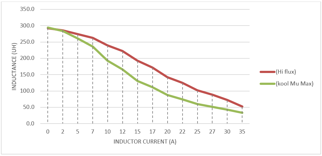
Toroid inductors with Kool Mμ Max (Mag-inc P/N: 0079894A7HT19) and high flux cores (Mag-inc P/N: C058894A2HT19) were selected and wounded with the same 44 turns to get around 240μH inductance at 0A current also meet the 33mm height requirement. The two inductors were then applied to the PFC boost stage one by one to test their inductance with current applied. Figure 2-2 shows that the inductor inductance using High Flux core is able to achieve our inductance target with less number of turns over the inductor using Kool Mμ Max core. Therefore, inductor with high flux core is selected in this design.
 Figure 2-2 Inductance Versus
Current