TIDT369A November 2023 – April 2024
2.3.5 Input Current Sensing
Ther are two current sensors in this design, but only 1 sensor is needed for PFC operation. The code supports both current sensors, seperated by a compiling flag, user can choose which sensor to use by changing the compiling flag and then re-download the code.
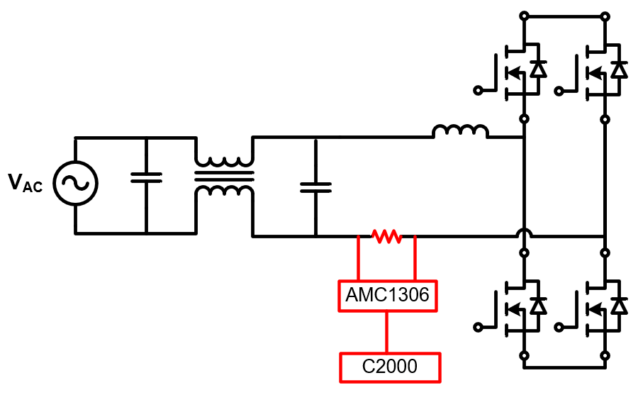
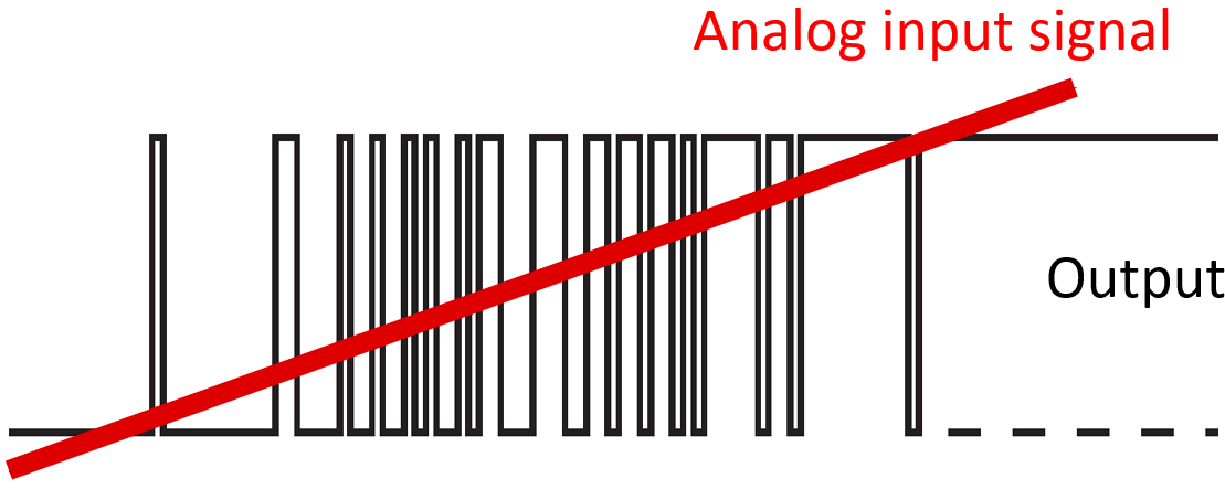
Option 1: Use an isolated Delta-Sigma modulator AMC1306 to sense input current (Figure 2-6). This is the deafult configuration in the code. The output of AMC1306 is a 1-bit stream, as shown in Figure 2-7. This 1-bit stream is sent to C2000 and decoded by a built-in delta-sigma digital filter. Two delta-sigma digital filters are used, one is configured with high speed but relatively low resolution for PFC current loop control, the other is configured with high resolution but relatively low speed for e-metering (Figure 2-8). For details of AMC1306 and E-meter, please refer to [2].
 Figure 2-6 Use AMC1306 for Current
Sensing
 Figure 2-7 AMC1306 Output
 Figure 2-8 Delta-Sigma Filter
Configuration
Figure 2-8 Delta-Sigma Filter
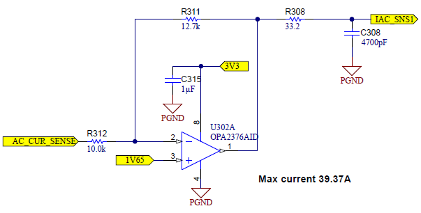
ConfigurationOption 2: Use a hall effect sensor TMCS1133 to sense input current. This is a conventional current sense method. The output of the hall sensor is amplified by a op-amp circuit (Figure 2-9). With sine wave AC input, the output of hall sensor is a sine wave with a DC offset. This signal is measured by C2000, then substract the DC offset to get the real AC input current signal.
 Figure 2-9 Current sense
amplifier