TIDT349 January 2024
- 1
- Description
- Features
- Applications
- 1Test Prerequisites
- 2Testing and Results
-
3Waveforms
- 3.1 Charge Mode Start-Up Waveform
- 3.2 OTG Mode Start-Up Waveform
- 3.3 Voltage Transition at OTG Mode
- 3.4 Ripple and Noise at OTG Mode
- 3.5 Load Transients at OTG Mode
- 3.6 Switching Waveform
- 3.7 Overcurrent Protection at OTG Mode
- 3.8 Short-Circuit Protection at OTG Mode
- 3.9 Short-Circuit Protection at Charge Mode
3.4 Ripple and Noise at OTG Mode
The following images show the ripple and noise at full load , 50%, 25%, and open load at 5V, 9V, 15V, and 20V conditions.
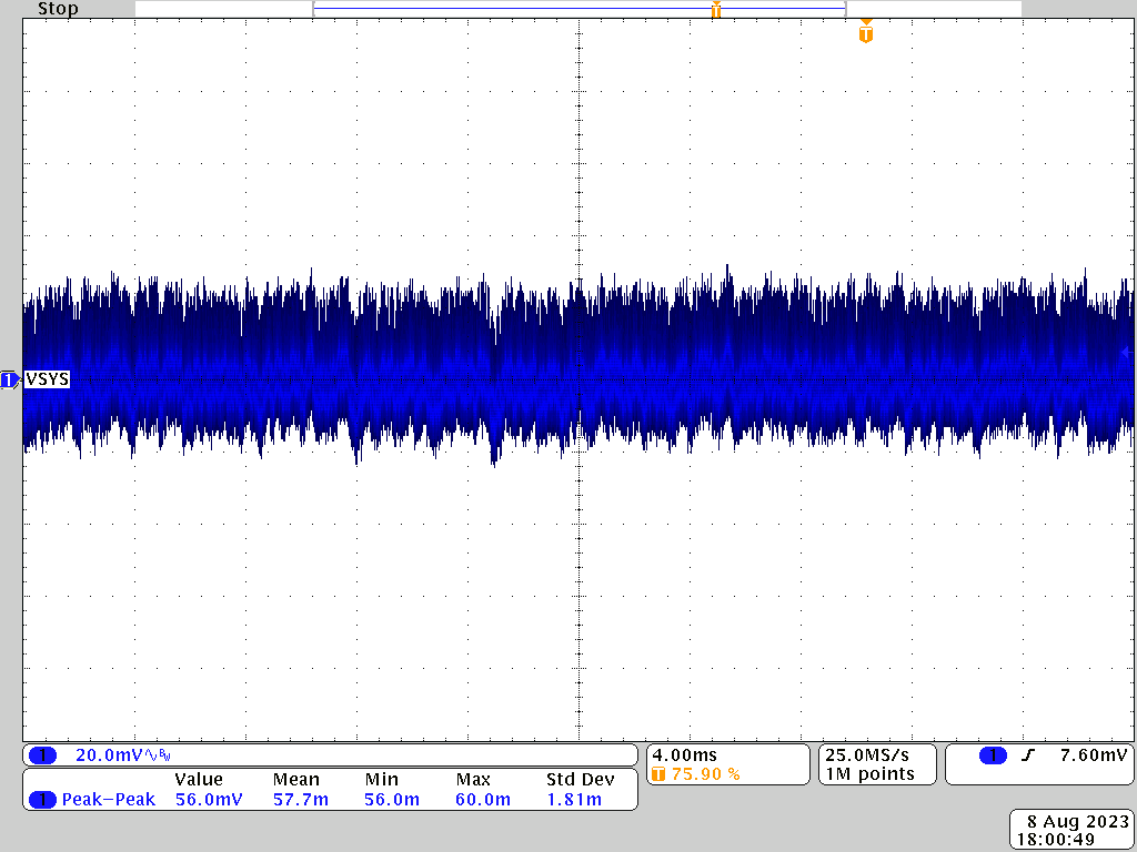 Figure 3-12 OTG Mode, 20V, 100% Load Ripple
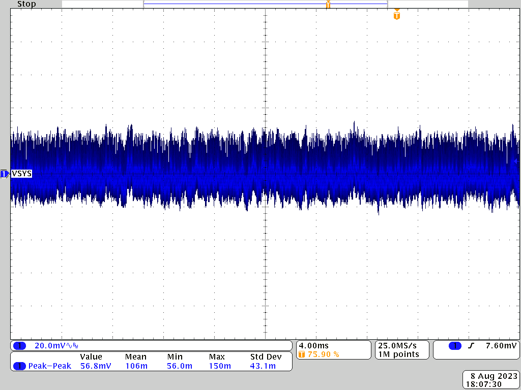 Figure 3-14 OTG Mode, 20V, 50% Load Ripple
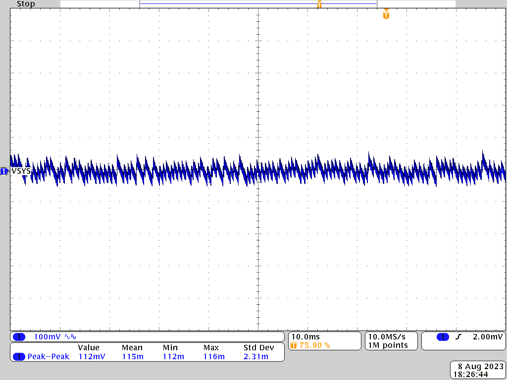 Figure 3-16 OTG Mode, 20V, Open Load Ripple
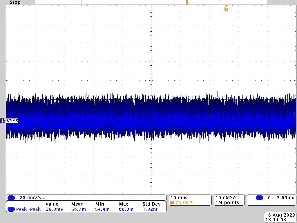 Figure 3-13 OTG Mode, 20V, 75% Load Ripple
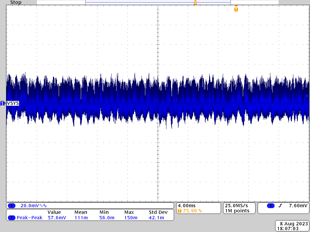 Figure 3-15 OTG Mode, 20V, 25% Load Ripple