TIDT316 December   2022


  1.   Description
  2.   Features
  3.   Applications
  4. 1Test Prerequisites
    1. 1.1 Voltage and Current Requirements
    2. 1.2 Considerations
    3. 1.3 Dimensions
  5. 2Testing and Results
    1. 2.1 Efficiency Graph
    2. 2.2 Loss Graph
    3. 2.3 Load Regulation
    4. 2.4 Line Regulation
    5. 2.5 Thermal Images
      1. 2.5.1 8-V Input Voltage
      2. 2.5.2 12-V Input Voltage
      3. 2.5.3 18-V Input Voltage
      4. 2.5.4 Conclusion
    6. 2.6 Bode Plots
      1. 2.6.1 5.2-V Input Voltage (Board Input, 5.0 V at Power Stage)
      2. 2.6.2 12-V Input Voltage
      3. 2.6.3 18-V Input Voltage
  6. 3Waveforms
    1. 3.1 Switching
      1. 3.1.1 Switchnode (SW) to GND
        1. 3.1.1.1 8-V Input Voltage
        2. 3.1.1.2 12-V Input Voltage
        3. 3.1.1.3 18-V Input Voltage
      2. 3.1.2 Diode D1 (Referenced to VOUT)
        1. 3.1.2.1 8-V Input Voltage
        2. 3.1.2.2 12-V Input Voltage
        3. 3.1.2.3 18-V Input Voltage
    2. 3.2 Output Voltage Ripple
    3. 3.3 Input Voltage Ripple (AC-Coupled)
      1. 3.3.1 Board Input
      2. 3.3.2 Power Stage Input
    4. 3.4 Load Transients
      1. 3.4.1 8-V Input Voltage
      2. 3.4.2 12-V Input Voltage
      3. 3.4.3 18-V Input Voltage
    5. 3.5 Start-Up Sequence
      1. 3.5.1 8-V Input Voltage
      2. 3.5.2 12-V Input Voltage
      3. 3.5.3 18-V Input Voltage
    6. 3.6 Shutdown Sequence
      1. 3.6.1 8-V Input Voltage
      2. 3.6.2 12-V Input Voltage
      3. 3.6.3 18-V Input Voltage
  7.   A Output Ripple Reduction, Output Current Capability, and Dithering Option
    1.     A.1 Output Ripple Reduction by Adding Ceramic Output Capacitors (MLCCs)
      1.      A.1.1 Initial Design
      2.      A.1.2 Adding one 47-µF X7R Ceramic Capacitor, MLCC, 10 V, X7R, 1210
      3.      A.1.3 Adding a Second 47-µF Capacitor (Final Design)
    2.     A.2 Maximum Output Current Capability at Ultra-Low Cold Cranking Using LM5157
    3.     A.3 Dithering Option via Resistor R10
      1.      A.3.1 Enabled
      2.      A.3.2 Disabled

Adding one 47-µF X7R Ceramic Capacitor, MLCC, 10 V, X7R, 1210

GUID-20221111-SS0I-CG3Z-J9K7-TR7GHZK39XPJ-low.jpg

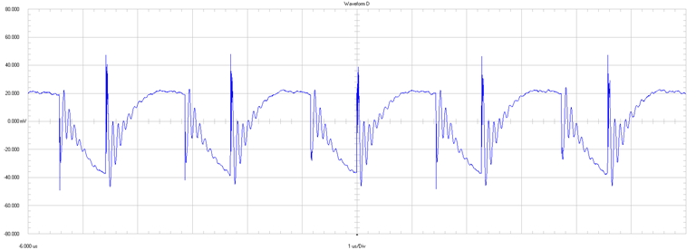
20 mV / div

1 µs / div

20-MHz bandwidth

Figure 4-2 Output Ripple Voltage of Initial Design and 1 × 47 µF at 12 VIN