TIDT307 October 2022
1.2 Considerations
- To simplify the measurement process, the three output rails were shorted together. This report considers a single output voltage of 9.0 V, 150 mA.
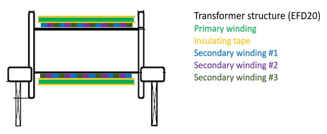
- Transformer structure: the three secondary windings were wired together to provide a high symmetrical structure.
 Figure 1-1 Transformer Structure
- Number of turns: primary winding (Np): 32, secondary windings (Ns): 36 (Coated copper wire, V 180 Ø, 0.20 mm)
- Measured inductance of primary winding: 5.9 µH (magnetizing), 1.59 µH (leakage)
- Measured inductance of secondary winding: 2.16 µH (leakage)