SWRU271I October   2010  – January 2020 CC2540 , CC2540T , CC2541 , CC2541-Q1 , CC2640R2F


  1.   Preface
    1.     Trademarks
    2.     Related Documentation
  2. 1Overview
    1. 1.1 Support Note
    2. 1.2 Introduction
    3. 1.3 Bluetooth Low Energy Protocol Stack Basics
  3. 2The TI Bluetooth Low Energy Software Development Platform
    1. 2.1 Overview
    2. 2.2 Configurations
    3. 2.3 Projects
    4. 2.4 Software Overview
  4. 3The Operating System Abstraction Layer (OSAL)
    1. 3.1 Overview
    2. 3.2 Task Initialization
    3. 3.3 Task Events and Event Processing
    4. 3.4 Heap Manager
    5. 3.5 OSAL Messages
  5. 4The Application and Profiles
    1. 4.1 Overview
    2. 4.2 Project Overview
    3. 4.3 Start-up in main()
    4. 4.4 Application Initialization
    5. 4.5 Event Processing
      1. 4.5.1 Periodic Event
      2. 4.5.2 OSAL Messages
    6. 4.6 Callbacks
    7. 4.7 Complete Attribute Table
    8. 4.8 Additional Sample Projects
  6. 5The Bluetooth Low Energy Protocol Stack
    1. 5.1 Overview
    2. 5.2 Generic Access Profile (GAP)
      1. 5.2.1 Overview
        1. 5.2.1.1 Connection Parameters
        2. 5.2.1.2 Effective Connection Interval
        3. 5.2.1.3 Connection Parameter Considerations
        4. 5.2.1.4 Connection Parameter Update
        5. 5.2.1.5 Connection Termination
      2. 5.2.2 GAP Abstraction
      3. 5.2.3 Configuring the GAP Layer
    3. 5.3 GAPRole Task
      1. 5.3.1 Peripheral Role
      2. 5.3.2 Central Role
    4. 5.4 Gap Bond Manager (GAPBondMgr)
      1. 5.4.1 Overview of Bluetooth Low Energy Security
      2. 5.4.2 Using the GapBondMgr Profile
      3. 5.4.3 GAPBondMgr Examples for Various Security Modes
        1. 5.4.3.1 Pairing Disabled
        2. 5.4.3.2 Just Works Pairing Without Bonding
        3. 5.4.3.3 Just Works Pairing With Bonding Enabled
        4. 5.4.3.4 Authenticated Pairing
        5. 5.4.3.5 Authenticated Pairing With Bonding Enabled
    5. 5.5 Generic Attribute Profile (GATT)
      1. 5.5.1 GATT Characteristics and Attributes
      2. 5.5.2 GATT Services and Profile
      3. 5.5.3 GATT Client Abstraction
        1. 5.5.3.1 Using the GATT Layer Directly
      4. 5.5.4 GATT Server Abstraction
        1. 5.5.4.1 GATTServApp Module
          1. 5.5.4.1.1 Building Up the Attribute Table
        2. 5.5.4.2 Profile Architecture
          1. 5.5.4.2.1 Attribute Table Definition
            1. 5.5.4.2.1.1 Service Declaration
            2. 5.5.4.2.1.2 Characteristic Declaration
            3. 5.5.4.2.1.3 Characteristic Value
            4. 5.5.4.2.1.4 Client Characteristic Configuration
          2. 5.5.4.2.2 Add Service Function
          3. 5.5.4.2.3 Register Application Callback Function
          4. 5.5.4.2.4 Read and Write Callback Functions
            1. 5.5.4.2.4.1 Read Request from A GATT Client
            2. 5.5.4.2.4.2 Write Request From Client
          5. 5.5.4.2.5 Get and Set Functions
    6. 5.6 L2CAP
    7. 5.7 HCI
      1. 5.7.1 HCI Extension Vendor-Specific Commands
      2. 5.7.2 Receiving HCI Extension Events in the Application
    8. 5.8 Library Files
  7. 6Drivers
    1. 6.1  Overview
    2. 6.2  ADC
    3. 6.3  AES
    4. 6.4  LCD
    5. 6.5  LED
    6. 6.6  KEY
    7. 6.7  DMA
    8. 6.8  UART and SPI
    9. 6.9  Other Peripherals
    10. 6.10 Simple NV (SNV)
  8. 7Creating a Custom Bluetooth Low Energy Application
    1. 7.1 Overview
    2. 7.2 Configuring the Bluetooth Low Energy Stack
    3. 7.3 Define Bluetooth Low Energy Behavior
    4. 7.4 Define Application Tasks
    5. 7.5 Configure Hardware Peripherals
    6. 7.6 Configuring Parameters for Custom Hardware
      1. 7.6.1 Board File
      2. 7.6.2 Adjusting for 32-MHz Crystal Stabilization Time
      3. 7.6.3 Setting the Sleep Clock Accuracy
    7. 7.7 Software Considerations
      1. 7.7.1 Memory Management for GATT Notifications and Indications
      2. 7.7.2 Limit Application Processing During Bluetooth Low Energy Activity
      3. 7.7.3 Global Interrupts
  9. 8Development and Debugging
    1. 8.1 Overview
    2. 8.2 IAR Overview
    3. 8.3 Using IAR Embedded Workbench
      1. 8.3.1 Open an Existing Project
      2. 8.3.2 Project Options, Configurations, and Defined Symbols
      3. 8.3.3 Building and Debugging a Project
      4. 8.3.4 Linker Map File
  10. 9General Information
    1. 9.1 Overview
    2. 9.2 Porting From BLE-Stack 1.5.0 to 1.5.1
    3. 9.3 Porting From BLE-Stack 1.4.2 to 1.5.0
    4. 9.4 Porting From Earlier BLE-Stack Versions
      1. 9.4.1 Porting BLEv1.4.1 Projects to BLEv1.4.2
      2. 9.4.2 Porting BLEv1.4.0 Projects to BLEv1.4.1
        1. 9.4.2.1 Project Porting Directions
        2. 9.4.2.2 API Changes
        3. 9.4.2.3 Typedef Changes
        4. 9.4.2.4 Structure Changes
          1. 9.4.2.4.1 Array Elements Changed to Pointers
          2. 9.4.2.4.2 Additional Fields in Key Distribution Strucutre
        5. 9.4.2.5 Default Value of HAL Components
        6. 9.4.2.6 Allocating Memory for Over-the-Air Messages
        7. 9.4.2.7 Allocation of Client Characteristic Configuration Table
      3. 9.4.3 Porting BLEv1.3.2 Projects to BLEv1.4.0
      4. 9.4.4 Porting BLEv1.2 Projects to BLEv1.3
      5. 9.4.5 Porting From CC2540 to CC2541 Project
    5. 9.5 Release Notes History
    6. 9.6 Document History
  11.   A GAP API
    1.     A.1 Commands
    2.     A.2 Configurable Parameters
    3.     A.3 Events
  12.   B GAPRole Peripheral Role API
    1.     B.1 Commands
    2.     B.2 Configurable Parameters
    3.     B.3 Callbacks
      1.      B.3.1 State Change Callback (pfnStateChange)
      2.      B.3.2 RSSI Callback (pfnRssiRead)
  13.   C GAPRole Central Role API
    1.     C.1 Commands
    2.     C.2 Configurable Parameters
    3.     C.3 Callbacks
      1.      C.3.1 RSSI Callback (rssiCB)
      2.      C.3.2 Central Event Callback (eventCB)
  14.   D GATT/ATT API
    1.     D.1 Overview
    2.     D.2 Server Commands
    3.     D.3 Client Commands
    4.     D.4 Return Values
    5.     D.5 Events
    6.     D.6 GATT Commands and Corresponding ATT Events
    7.     D.7 ATT_ERROR_RSP Error Codes
  15.   E GATTServApp API
    1.     E.1 Overview
    2.     E.2 Commands
  16.   F GAPBondMgr API
    1.     F.1 Overview
    2.     F.2 Commands
    3.     F.3 Configurable Parameters
    4.     F.4 Callbacks
      1.      F.4.1 Passcode Callback (passcodeCB)
      2.      F.4.2 Pairing State Callback (pairStateCB)
  17.   G HCI Extension API
    1.     G.1 Overview
    2.     G.2 Commands
    3.     G.3 Host Error Codes
  18.   Revision History

Connection Parameters

This section describes the connection parameters sent by the initiating device with the connection request. These parameters can be modified by either device when the connection is established.

These parameters are the following:

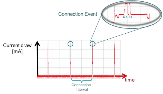
  • Connection Interval – Bluetooth Low Energy connections use a frequency-hopping scheme. The devices send and receive data on a specific channel at a specific time and meet at a new channel later. The link layer of the Bluetooth Low Energy protocol stack handles the channel switching. This meeting, where the two devices send and receive data, is a connection event. If there is no application data sent or received, the devices exchange link layer data to maintain the connection. The connection interval is the time between two connection events in units of 1.25 ms. The connection interval can range from a minimum value of 6 (7.5 ms) to a maximum of 3200 (4.0 seconds).
  • figure_09_swru271.gifFigure 5-2 Connection Event and Interval

    Applications may require different connection intervals. This difference affects the power consumption of the device. For more detailed information on power consumption, see the Measuring Power Consumption.
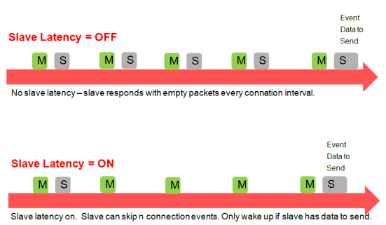
  • Slave Latency – This parameter lets the slave (peripheral) device skip several connection events. If the device has no data to send, it can skip connection events and deactivate its radio during the connection event, which saves power. The slave latency value represents the maximum number of events that can be skipped. This value ranges from a minimum value of 0 (no connection events)) to a maximum of 499. The maximum value must create an effective connection interval less than 16 seconds. For an overview of this parameter, see Figure 5-3.
  • figure_10_swru271.gifFigure 5-3 Slave Latency
  • Supervision Time-out – This parameter is the maximum time period between two successful connection events. If this time period passes without a successful connection event, the device considers the connection lost and returns to an unconnected state. This parameter value is represented in units of 10 ms. The supervision time-out value can range from a minimum of 10 (100 ms) to 3200 (32 seconds). The time-out must be larger than the effective connection interval. For more details, see Section 5.2.1.2.