SWRA733 March 2022 WL1807MOD , WL1837MOD
2.2 MRMC Single Radio Network Topology
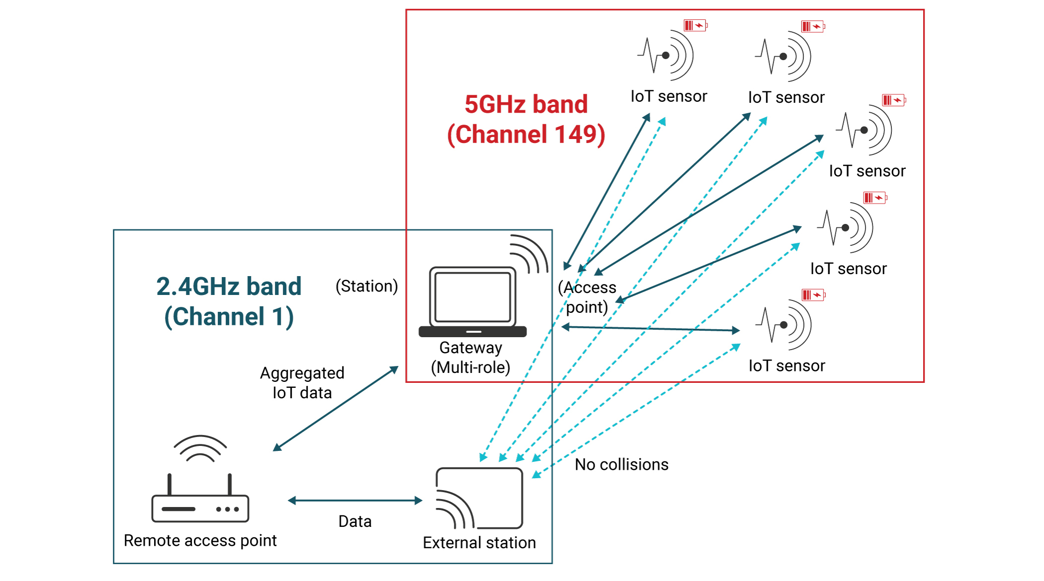
The following example will demonstrate the Multi-Role Multi-Channel use case and how system efficiency is significantly improved when roles are operating on different channels or bands. As can be seen in the Figure 2-2 below, the traffic does not overlap and no collisions between the IoT STAs connected to the Multi-Role device Access Point (“Red network”) and the Remote Station connected to the Remote Access Point (“Blue network”). Thus, overall system throughput is higher (very important for heavy data consumers). In addition, the system’s overall power consumption is lower as the amount of re-transmissions required from all the devices is lower compared to a single channel (very important for IoT nodes).
 Figure 2-2 Multi-Role Multi-Channel Network Topology