SPRAD13 May 2022 AM623 , AM625
- Abstract
- Trademarks
- 1 Introduction
- 2 Via Channel Arrays
- 3 Width/Spacing Proposal for Escapes
- 4 Stackup
- 5 Via Sharing
- 6 Floorplan Component Placement
- 7 Critical Interfaces Impact Placement
- 8 Routing Priority
- 9 SerDes Interfaces
- 10DDR Interfaces
- 11Power Decoupling
- 12Route Lowest Priority Interfaces Last
- 13Summary
5 Via Sharing
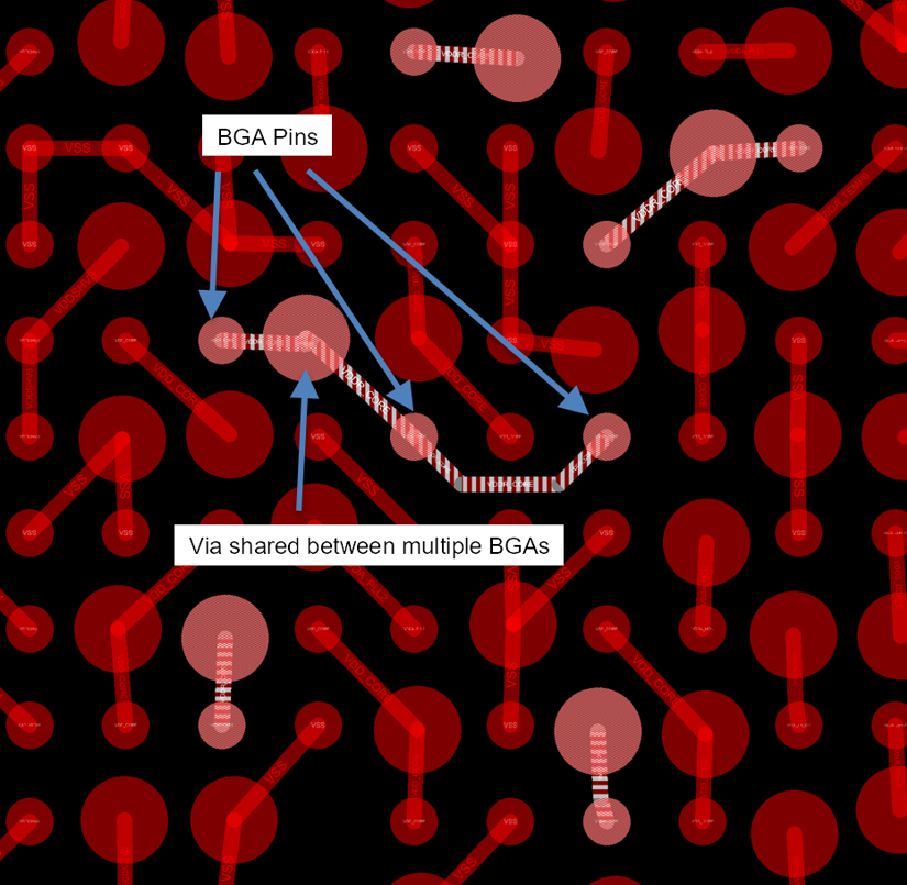
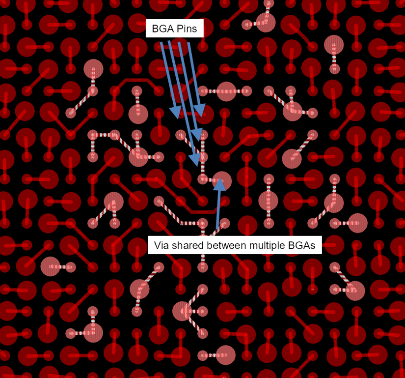
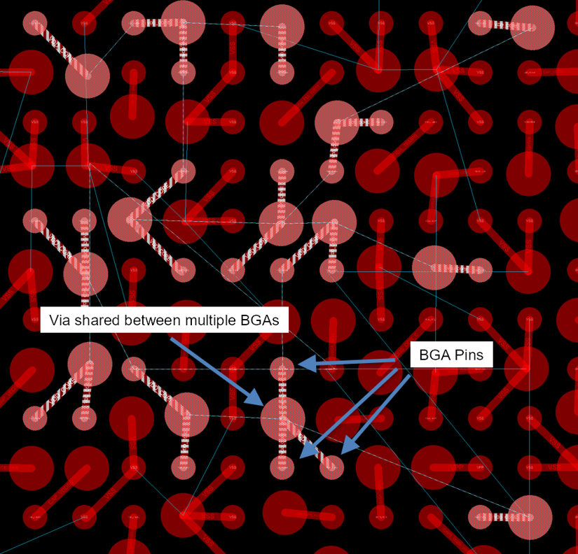
The Via Channel Array BGA pattern implemented on the AM62 design offers several opportunities for via sharing. Vias are shared across BGA pins. Figure 5-1 and Figure 5-2 show the via sharing opportunities for VDDR_CORE and VSS domains, respectively. Figure 5-1 assumes that VDD_CORE and VDDR_CORE domains are separate. If these domains are merged, more via sharing opportunities are presented, as shown in Figure 5-3. Via sharing across BGA pins provides for easier escape routing and also stronger electrical connections by connecting multiple pins.
 Figure 5-1 Via Sharing for VDDR_CORE Domain
 Figure 5-2 Via Sharing for VSS
 Figure 5-3 Via Sharing for Merged VDD_CORE and VDDR_CORE Domains