SNVAA21 August 2021 LM61480-Q1 , LM61495-Q1 , LM62460 , LM62460-Q1
2 Different Types of Current Sensing
Two Types of Current Sensing
Two commonly used methods for sensing current in the power stage of a buck converter are the use of current sense resistors and inductor DCR current sensing. The benefit of using the current sense resistor method is superior accuracy over the entire operating conditions (for example, variations in inductor DCR and inductance values between the two channels) and better matched current sharing between the two phases, while sacrificing power loss. On the other hand, DCR current sensing sacrifices accuracy while being more efficient, since there is typically negligible power loss associated with this method of sensing. The application requirements will dictate which current sensing method will be implemented.
Inductor DCR Current Sensing
When using the inductor DCR current sensing method, a carefully selected RC network is used to mimic or recreate the voltage that would be seen across the DCR of the inductor. It is as if the DCR of the inductor is the current sense resistor. In order to accurately represent the current flowing through the DCR, the RC time constant (τ), needs to be the same as that of the inductor and DCR
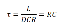
- L = power inductor
- DCR = inductor direct-current-resistance
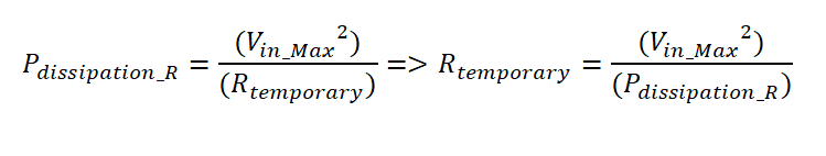
One of the ways to find the values for the RC components is by first calculating an approximate resistor value for R (Rtemporary), from which we will find the capacitor value. Once an actual capacitor is selected (i.e from a component vendor), we can then re-calculate a more accurate resistor value. The reason for performing this slightly iterative process is due to the fact that it is usually more difficult to find a capacitor with the desired value, temperature coefficient, voltage rating, and availability, compared to the resistor.
- Calculate a temporary resistor value: A good-sized resistor for most applications is either an 0402 or 0603 (Imperial) package size resistor. For most applications 0402 resistors will work fine. The characteristics of these (0402) resistors vary between manufacturers and product-series, however they usually have voltage ratings of about 50V and power ratings of about 1/16W, or 0.063W. Worst-case power dissipation estimation, along with buffers, let us say is 50mW for this 0402-package resistorEquation 2.
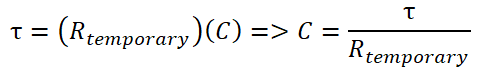
- Calculate a capacitor value:Equation 3.
- Find an actual capacitor that is closest to that calculated in Step 2
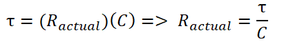
- Calculate the actual resistor value to be selected/used:Equation 4.
Current Sense Resistor for Current Sensing
The power loss through the current sense resistor involves the maximum continuous load current, which for a buck converter is the average inductor current at this condition.

For example, in the case of PMP22993, the maximum peak load current (per phase) is 6A, giving us a peak inductor current of 7AIL_pk. Figure 2-1 is a GUI from the Power Stage Designer Tool to help illustrate and simulate the expected inductor current given a typical design value (VIN = 16V, VOUT = 3.3V, IOUT = 6A, Fsw = 2.1MHz).
 Figure 2-1 Inductor Current
Simulation from Power State Designer Tool
Figure 2-1 Inductor Current
Simulation from Power State Designer ToolIf we were to use 100mV as the full-scale current sense voltage we get,
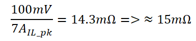
Now let us see how much power will be dissipated in this resistor when operating at the maximum continuous load current:
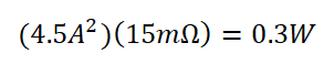
Let us check how much this amount of power loss will decrease our total system efficiency:
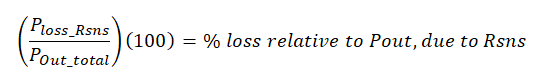
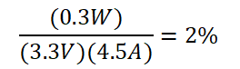
For this application, a loss of 2% of efficiency at maximum continuous load is deemed acceptable. Designing for a reduced system efficiency of 3% or lower is generally acceptable but will depend on the application requirements. As a rule-of-thumb, it is always good to select a current sense resistor that has a power dissipation rating that is twice that of the calculated power loss. This is so that the resistor temperature does not get too high.
To assist in calculating, as well as visualizing, many of the signals associated with switch-mode power supplies, such as the peak inductor current, please download Power Stage Designer (link).