SNVAA21 August 2021 LM61480-Q1 , LM61495-Q1 , LM62460 , LM62460-Q1
3 Basic Current Sharing Operation
Current sharing between two buck regulators can be achieved using a simple current sharing op-amp circuit using a OPA991. This current sharing amplifier design is configured as a differential amplifier which compares the primary and secondary phase inductor currents. The op amp circuit servos the secondary converter's load current, by controlling the output voltage, to keep the difference between the primary and secondary output currents zero. For example, if the primary phase were to source more current than the secondary phase, the output of the differential amplifier will decrease causing the secondary phase voltage to slightly increase. This results in the secondary phase sourcing more current until it achieves balanced current sharing.
R2 and RF should be calculated such that, when the primary and secondary output voltage is matched, the output of the difference amplifier is equal to the reference voltage (Vref) of the buck regulator (Refer to schematic in Figure 3-1 for more details). When both phases are evenly matched no current will be sourced or sinked from the feedback node. Note that the op-amp current sense design requires a compensation capacitor that is placed in parallel to RF. This capacitor value may need to be adjusted per application parameters.
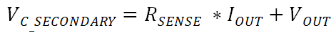
- VC_SECONDARY is the voltage before the current sense resistor of the secondary converter
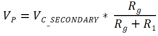
- Note: This equation assumes the ideal op-amp voltage on both inverting and non-inverting inputs
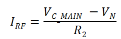
- VC_MAIN is the voltage before the current sense resistor of the main converter
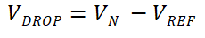
- VREF is the internal reference voltage of the converter
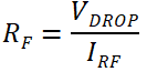
 Figure 3-1 Current Sharing Differential Op-Amp Circuit Design