SNOA993A June 2018 – July 2021 LDC2112 , LDC2114 , LDC3114 , LDC3114-Q1
2.2 Button Sequencing and Error Handling
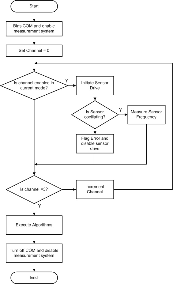
The LDC211x and LDC3114 start sampling channel 0 and check to see if it is enabled. If the channel is enabled, it starts the sensor oscillation and checks whether the sensor is oscillating. If so, it measures the sensor frequency, otherwise the device flags an error. It then increments to the next channel, and repeats the process. Figure 2-2 represents this sequence as a flowchart.
If the sensor cannot oscillate in a stable manner, the device flags the error in STATUS:LC_WD and continues onto the next channel. Potential sources of a LC_WD error include the sensor frequency exceeds the sensor maximum frequency of 30 MHz, sensor frequency is below the minimum specified sensor frequency, or the sensor RP is less than the minimum supported RP.
The LDC211x and LDC3114 devices are intended to maintain operation under a wide range of conditions, and may not generate an error condition even if the sensor is not within the specified operating region. Refer to Figure 4-1 for details on the Execute Algorithms operation shown in Figure 2-2.
 Figure 2-2 Sampling Flow Chart