SNOA993A June 2018 – July 2021 LDC2112 , LDC2114 , LDC3114 , LDC3114-Q1
2 Scan Rate and Sampling Interval
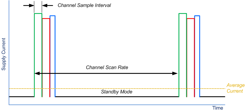
Once the LDC211x or LDC3114 powers on, it continuously samples the enabled channels and returns to as shown in Figure 2-1. The active channels, sample time interval, and button scan rate are all configurable parameters. Refer to Table 2-1 for a listing of the device parameters that control the Scan Rate and Sample Interval. A higher Scan Rate produces a more responsive interface, but generally at the cost of higher average supply current consumption. Note that the scan rate can vary by up to ±30% from the nominal value across devices.
 Figure 2-1 Sample Interval and Scan
Rate
Figure 2-1 Sample Interval and Scan
Rate| Device Parameter | Configuration Effect | Details |
|---|---|---|
| SENCYCx | Button Sample Interval for channel x | Each channel has dedicated setting. Sensor frequency is used to determine proper setting. |
| CNTSCx | Button Sample Interval for channel x | Each channel has dedicated setting. Sensor frequency, LCDIV, and SENCYCx is used to determine proper setting |
| LCDIV | Button Sample interval for all channels | Common setting for all channels |
| LPWRB pin | Button Scan Interval | When set High, device samples based on NPSR value. When set Low, device sample based on LPSR value. |
| NPSR | Button Scan Interval | When LPWRB pin is High, this field sets the device scan rate from 10 sps to 80 sps. |
| LPSR | Button Scan Interval | When LPWRB pin is Low, this field sets the device scan rate from 0.625 sps to 5 sps. |
The Button Sample Interval is a function of the SENCYCx, LCDIV, and the Sensor Oscillation Frequency. The sample time, tSAMPLE is set by:
tSAMPLE = 128 × (SENCYCx+1)×2LCDIV ÷ ƒSENSORx
The recommended sample interval is 1 ms, as this provides a good balance on noise vs. supply current. Shorter sample intervals may have reduced SNR. Variations in sensor frequency greater than 2.5% may need to use different settings for SENCYCx. If the sensor frequency increases significantly and the SENCYCx & LCDIV settings are not changed, then a reduction in sensitivity can occur. Alternatively, if the sensor frequency decreases by ~30% from the configured frequency, it is possible for internal counters in the device to over-range, resulting in improper operation.