SNLU245 February 2019
4.1 USB2ANY GUI Installation
Follow the steps below to install the USB2ANY software and confirm the GUI to ONET1130EC-EVM communication.
- Install the USB2ANY GUI onto the computer and follow the instructions to install this software.
- Check the USB2ANY packaging for the box and cables necessary to set up the ONET1130EC-EVM. Figure 5 shows the required USB2ANY hardware.
- Connect the USB2ANY 10-pin cable to the USB2ANY box as shown in Figure 6. Connect the other side of the 10-pin cable need to J28 on the ONET1130EC-EVM. Note that this cable is locked.
- Start the USB2ANY GUI and make sure the GUI authenticates the USB2ANY box. The GUI should show the serial number and firmware revision as shown in Figure 7.
- Click on the USB2ANY tab and change the slave address to 0x08 and turn on 3.3-V supply as shown in Figure 8.
- Make sure the internal address is set to 00 and click the "Read" button. If the read data is "41," the GUI and ONET1130EC-EVM have reliable communication. See Figure 9
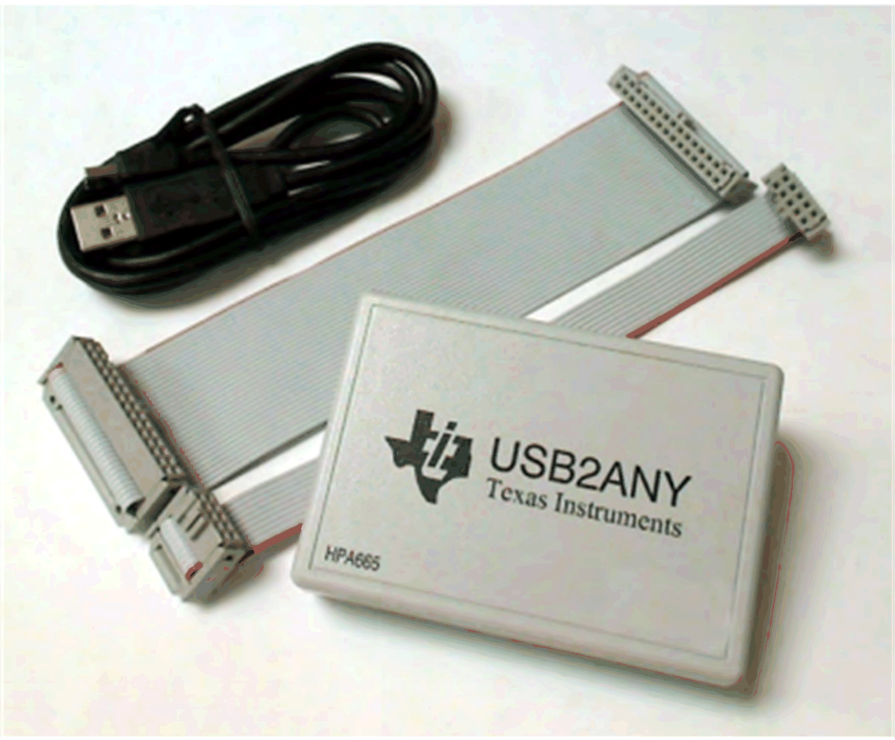 Figure 5. USB2ANY Box and Cables
 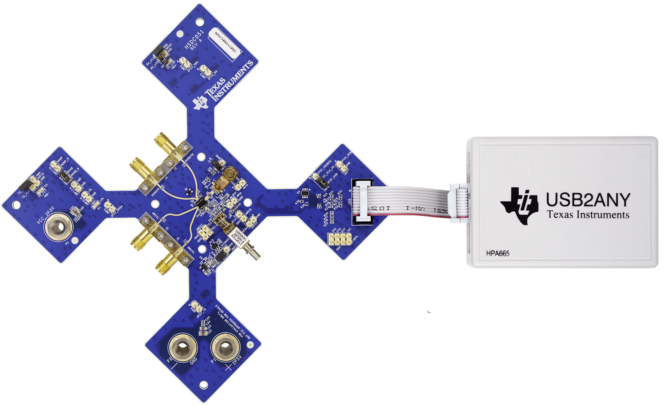 Figure 6. Cable Connected to USB2ANY
 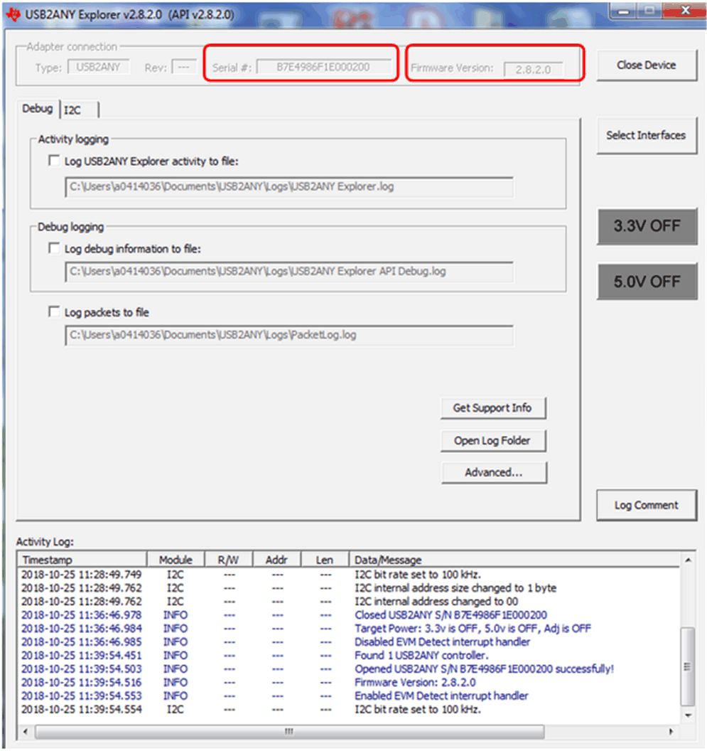 Figure 7. USB2ANY Box Serial Number and Firmware Revision
 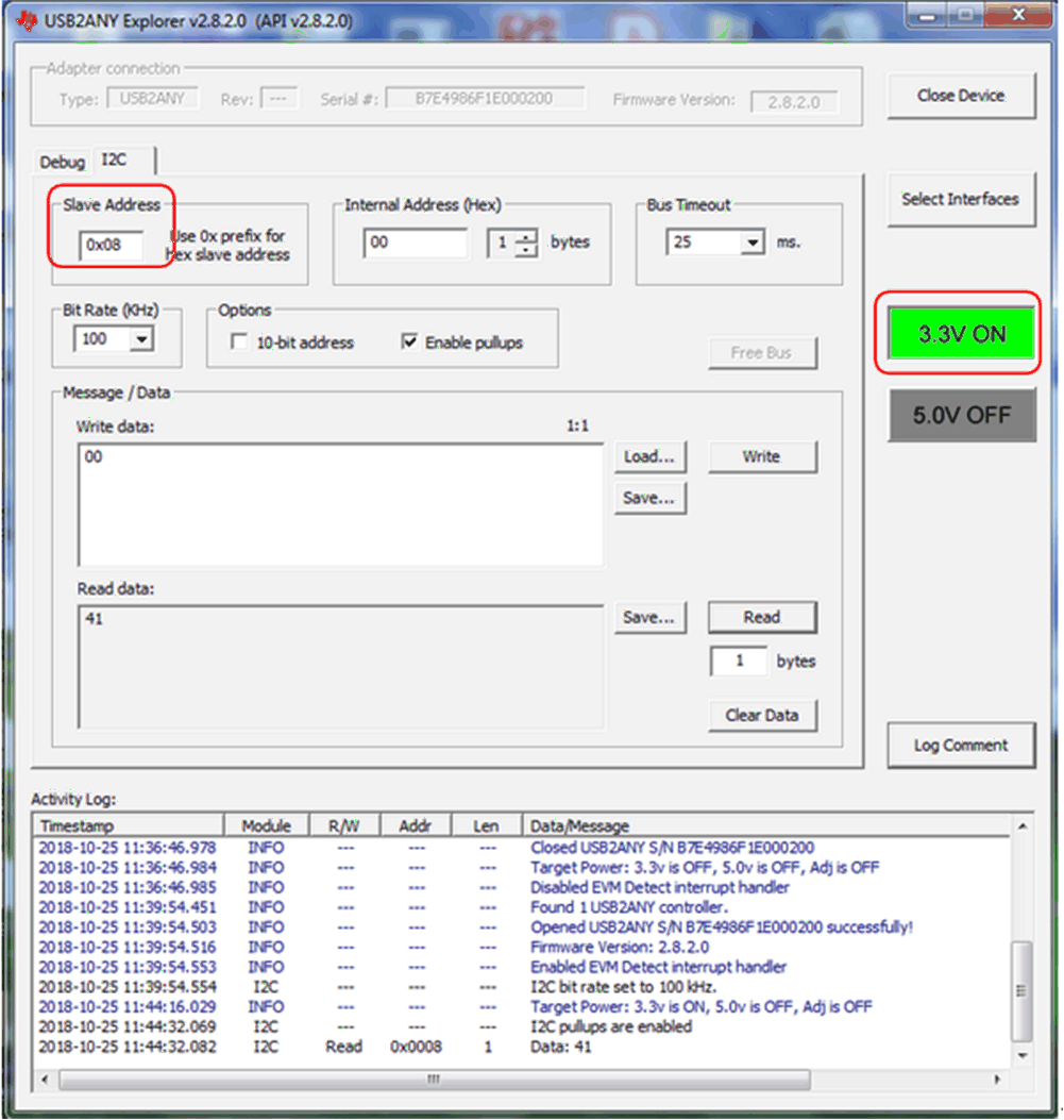 Figure 8. USB2ANY Slave Address
 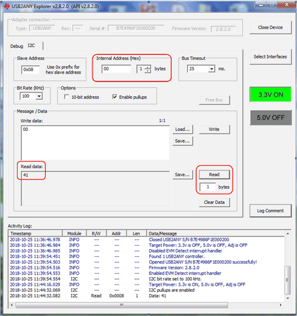 Figure 9. USB2ANY GUI to ONET1130EC-EVM Reliable Communication
 Follow these steps to gather ONET1130EC-EVM measurements:
- Solder the ROSA and TOSA onto the EVM.
- Connect a differential data input signal source to the SMA connectors TXINP/TXINN through 50-Ω matched impedance cables. Set the data rate between 9.8 Gbps and 11.7 Gbps. Set the amplitude between 100mVp-p differential and 1000mVp-p differential.
- Connect the output SMA connectors RXOUP/RXOUTN through 50-Ω matched impedance cables to a digital communications analyzer (DCA).
- Connect the USB dongle to the EVM and attach the interface cable from the USB port of the computer to the mini-B USB port of the dongle.
- Apply a +2.5-V supply to the +2.5-V banana jack and connect the supply ground to the GND banana jack.
- Apply a negative bias voltage in the range of –0.4 V to –1.5 V for the EML to JMP28. The required voltage is TOSA-dependent.
- Connect the TOSA thermistor at JMP24 to the TEC controller.
- Connect the TEC+ and TEC– at JMP27 to the TEC controller.
- Connect the TOSA to the optical input of a DCA through a single-mode fiber patch cord.
- Connect an optical input source to the ROSA through a single-mode fiber patch cord.
Figure 10 shows a typical setup.
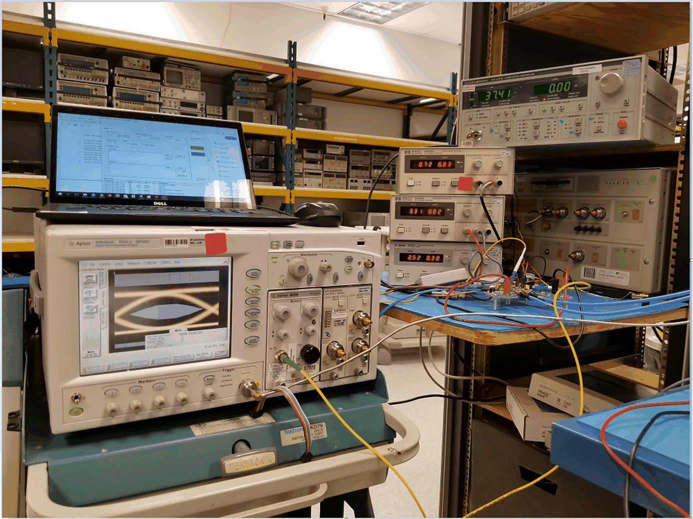 Figure 10. Typical ONET1130EC-EVM Setup