SNLU245 February 2019
3 EVM Connections
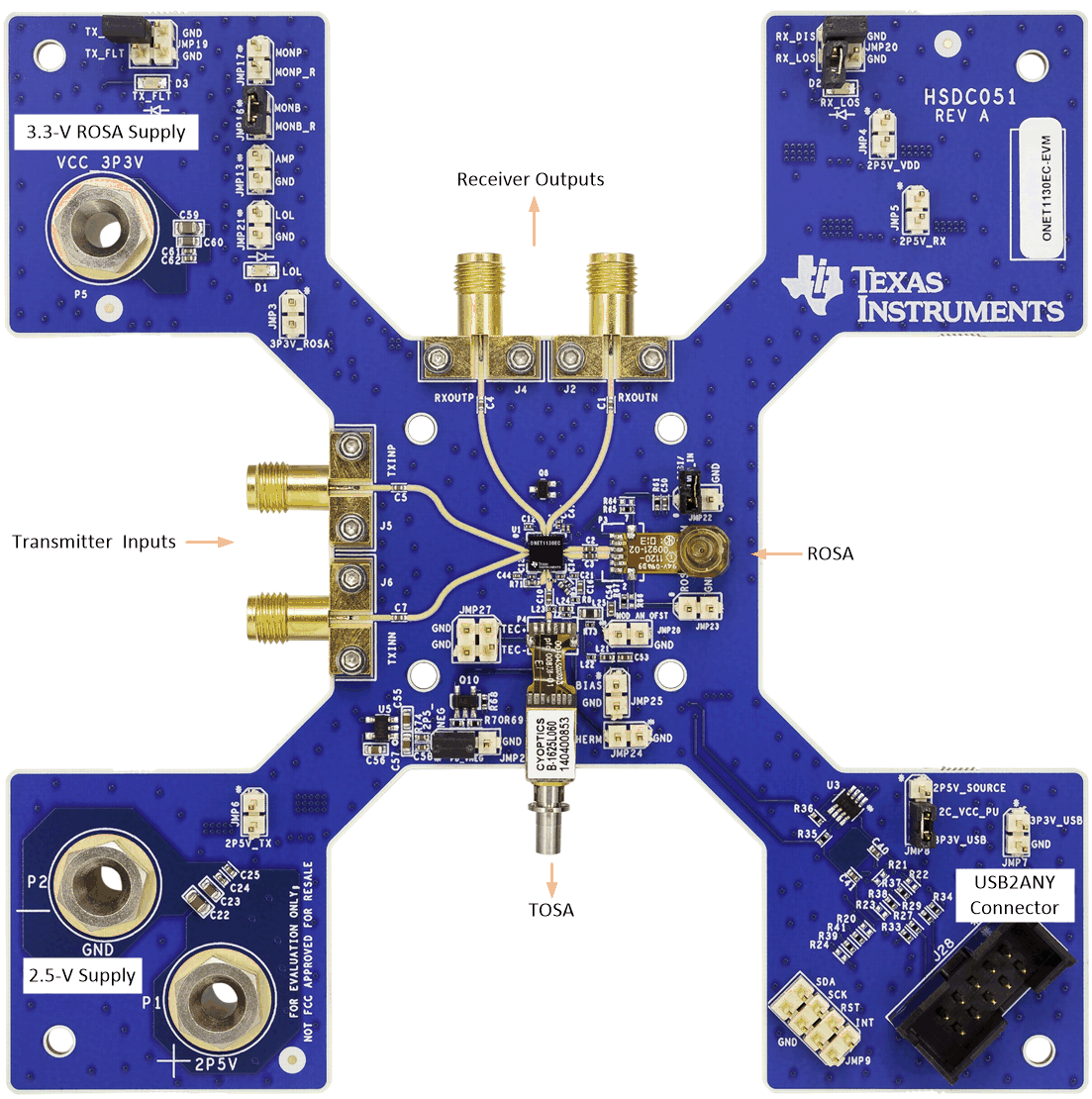
Figure 3 shows the location of the major inputs and outputs on the EVM board.
 Figure 3. ONET1130EC-EVM Connections
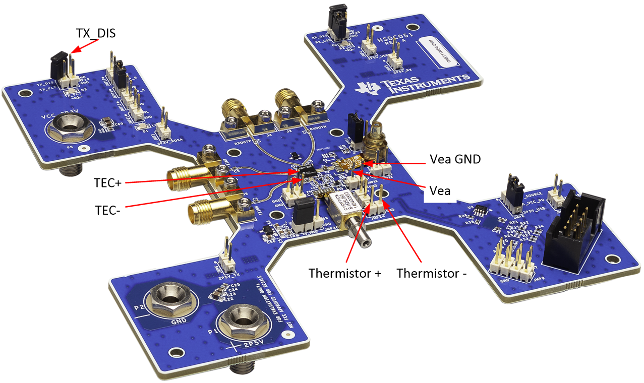
 A ROSA and TOSA are to be supplied by the user. In addition, connections for the EML bias voltage and TEC controller are also required. Figure 4 shows the locations for the ROSA and TOSA, EML bias voltage, TOSA thermistor, and the TEC+ and TEC– connections to the TEC controller.
 Figure 4. ONET1130EC-EVM Connections