SNAU198A May 2016 – May 2016 TDC7201
5.1 TDC7201EVM Connections
- If you haven’t done so, connect the USB cable from the MSP430 Launch Pad to your PC.
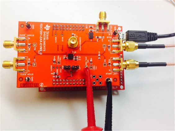
- If you haven't done so, connect the TDC7201EVM to the MSP430 Launch Pad via J1 and J2 as shown in Figure 6.
- Setting the Dual Channel Function Generator:
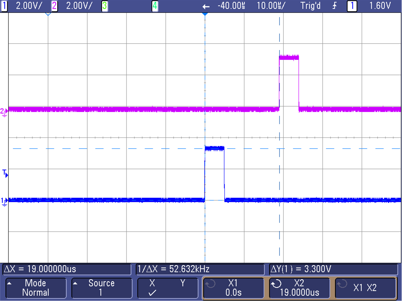
- Set channel 1 of the dual function generator to the following (see Figure 5):
- Pulse 1-Cycle
- Burst mode
- Freq = 40 kHz
- Delay = 0 s
- Amplitude = 3.3 Vpp
- Offset = 1.65 V
- Duty = 20%
- Burst Trigger Source = External
- Set channel 2 of the dual function generator to the following (see Figure 5):
- Pulse 1-Cycle
- Burst mode
- Freq = 40 kHz
- Delay = 19 µs --> this is the time-of-flight (TOF)
- Amplitude = 3.3 Vpp
- Offset = 1.65 V
- Duty = 20%
- Burst Trigger Source = External
 Figure 5. START and STOP Signals Scope Shot
 - Set channel 1 of the dual function generator to the following (see Figure 5):
- Connecting the Input Signal:
- Using a USB-to-SMA cable, connect channel 1 of the dual function generator to TDC7201EVM’s START1_EXT connector (J5).
- Using a USB-to-SMA cable, connect channel 2 of the dual function generator to TDC7201EVM’s STOP1_EXT connector (J4). See Figure 6.
- Connecting the Trigger Input:
 Figure 6. TDC7201EVM Connection Setup
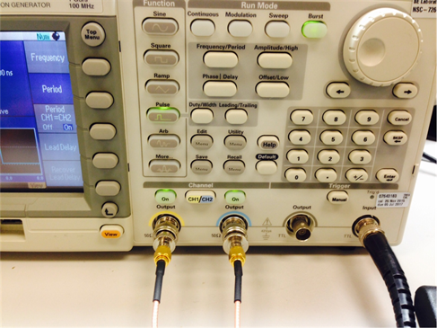
  Figure 7. Tektronix AFG3102 Connections