SNAA366 October 2022 LMX1204
3.2 AFE7950 Clocking Measurement Results
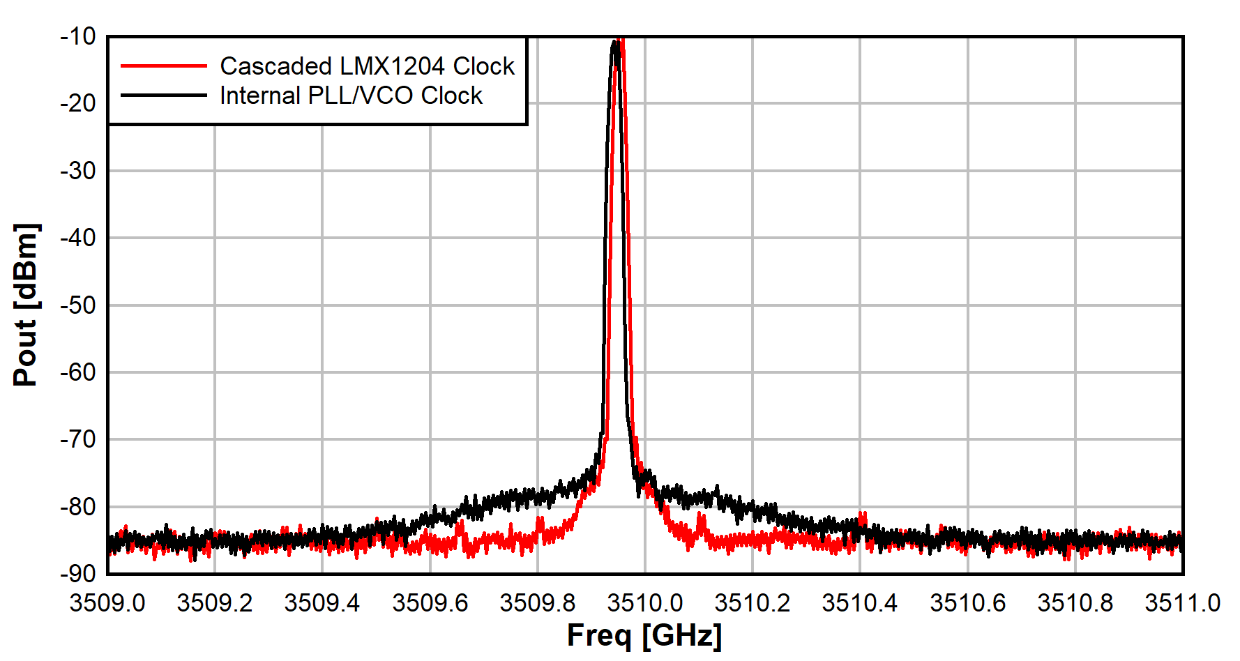
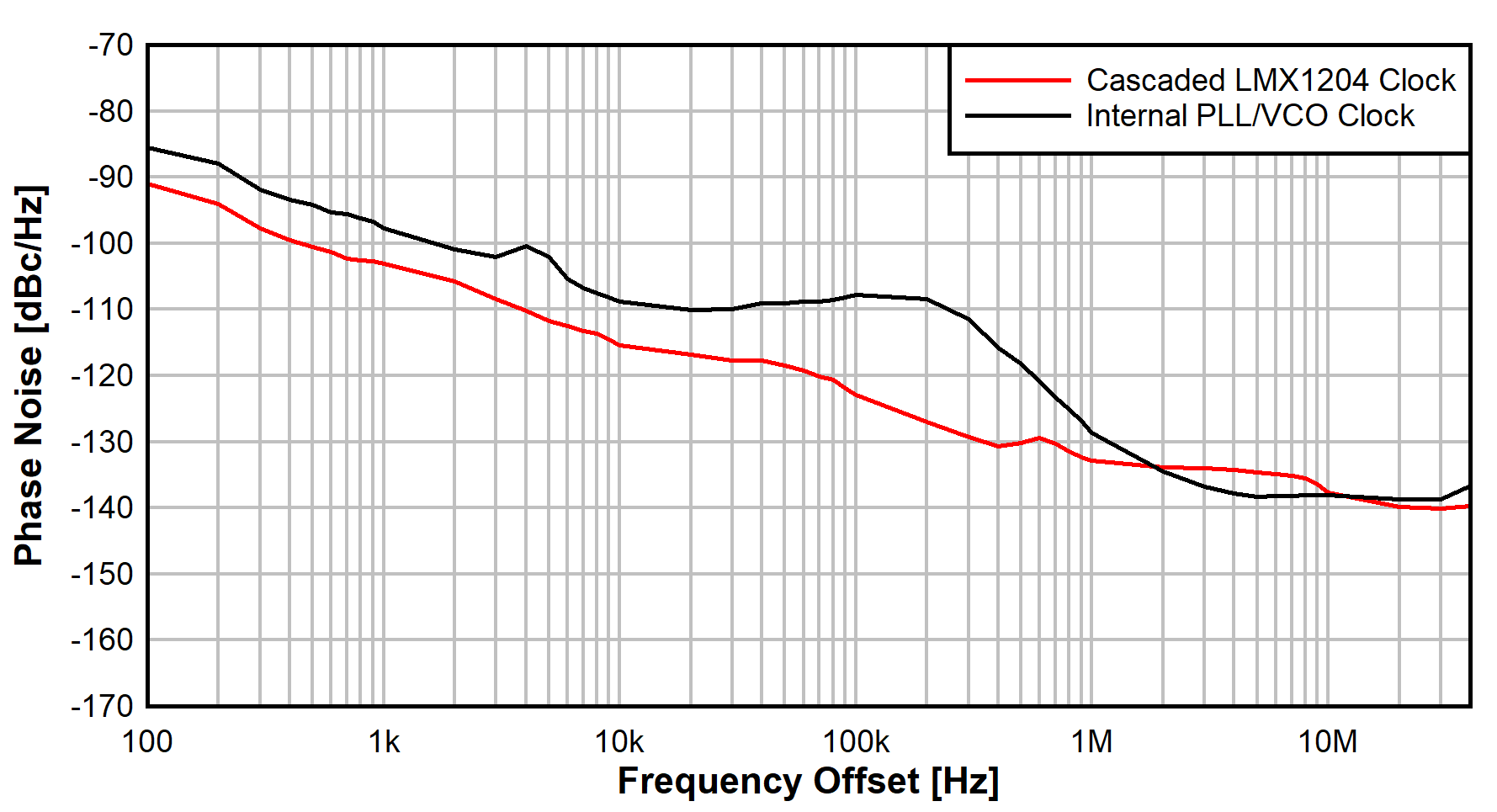
Measurement results compare output phase-noise performance from the transmitter between the cascaded LMX1204 approach (with multiplier) and the internal PLL/VCO. Figure 3-3 shows the spectrum output comparison between the two options. Since the baseband signal is slightly under 10 MHz, the output tone resides just below 3510 MHz. The close-in spectrum performance of the cascaded LMX1204 with multiplier is better than that of the internal PLL/VCO operating at the same clock rate and same output frequency. Figure 3-4 shows the output phase noise plot measured with the Agilent PSA spectrum analyzer with phase-noise option to provide a relative comparison between the close-in phase-noise performance. As evident before, the cascaded LMX1204 approach yields a better close-in performance and equivalent farther out noise=floor performance.
 Figure 3-3 AFE7950 Output Spectrum
Comparison
 Figure 3-4 AFE7950 Signal Output Phase
Noise Comparison