SLVUCA1 November   2021 TPS7H1210-SEP


  1.   Trademarks
  2. 1Introduction
    1. 1.1 Features
    2. 1.2 Applications
  3. 2Setup
    1. 2.1 Input/Output Connectors and Jumper Descriptions
      1. 2.1.1 J1, J4 (–)VIN
      2. 2.1.2 J6 GND
      3. 2.1.3 J2, J5 (–)VOUT
      4. 2.1.4 J7 GND
      5. 2.1.5 J3 EN
      6. 2.1.6 TP1-5 Test Points
    2. 2.2 Equipment Setup
  4. 3Operation
  5. 4Adjustable Operation
  6. 5Test Results
    1. 5.1 Enable, Disable, and Soft Start Timing
    2. 5.2 Output Load Transients
    3. 5.3 PSRR
    4. 5.4 Noise Spectral Density
  7. 6Board Layout
  8. 7Schematic and Bill of Materials

Enable, Disable, and Soft Start Timing

Figure 5-1 shows the enable and disable characteristic where –VIN is –6 V, EN is toggled from ground to –2.4 V while the output drives a 1-A load. The waveform for VFB is also shown for reference. CNR_SS of 100 nF results in a soft start time of approximately 120 ms.
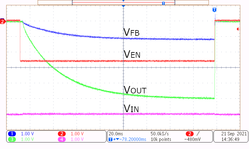
GUID-20211029-SS0I-2PJD-TGNK-P3WMVPXF3JZR-low.png Figure 5-1 Enable and Disable Timing