SLVAF55 July 2021 TPS62130 , TPS62901 , TPS62902 , TPS62903
3.3 VSET
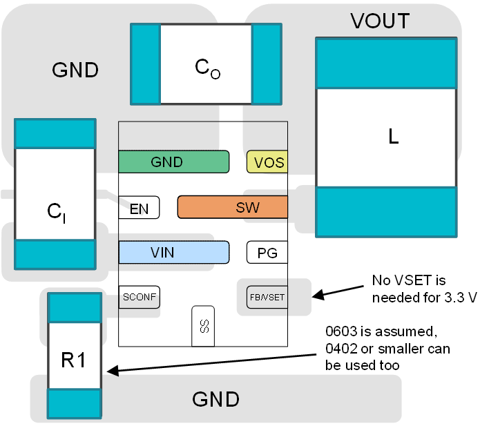
Using the SCONFIG pin in conjunction with the FB/VSET pin, can be used to save an additional one or two resistors when setting the output voltage. Typically, to set an output voltage, a resistor divider is used on the feedback pin. The advantage to using the resistor divider is you are able to choose any output value in the output voltage range. Both the TPS621x0 and TPS6290x have the ability to use a resistor divider to configure the Vout. Several applications use common voltages at point of load, so TPS6290x has added the ability to select an output value from one of 16 common voltages preset options through the VSET function. These values vary from 0.4 V to 5.5 V. If one of those preset output voltages is desired for a design, the VSET function can be used to save one or even both resistors (if left floating) when configuring the output voltage, as shown in Figure 3-3. The resulting total solution size is 25mm2.
 Figure 3-3 Configuration for the Smallest Solution Size Using TPS6290x