SLVAEZ0 November 2020 TPS1H000-Q1 , TPS1H100-Q1 , TPS1H200A-Q1 , TPS1HA08-Q1 , TPS1HB35-Q1 , TPS2H000-Q1 , TPS2H160-Q1 , TPS2HB16-Q1 , TPS2HB50-Q1 , TPS4H000-Q1 , TPS4H160-Q1
2.1 Basics of PSpice - Modifying Components
Within the schematic, is it possible to modify schematic in ways such as modifying the supply power, V1, controlling the enable time using V2 power supply, and add the characteristics to the load that the device will be powering.
To accurately model operating conditions, the ambient temperature can be modified by editing the “TEMP_AMB” property that has been added. This property refers to the ambient temperature or surrounding temperature that the device will be operating in.
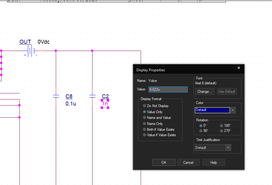
To modify parts already on the schematic, double clicking the part and modifying the property or double clicking on the parameter to be changed and modify the value as shown in Figure 2-2.
 Figure 2-2 Changing Value of Capacitor in PSpice