SLVAEZ0 November 2020 TPS1H000-Q1 , TPS1H100-Q1 , TPS1H200A-Q1 , TPS1HA08-Q1 , TPS1HB35-Q1 , TPS2H000-Q1 , TPS2H160-Q1 , TPS2HB16-Q1 , TPS2HB50-Q1 , TPS4H000-Q1 , TPS4H160-Q1
2.3 Basics of PSpice - Running Simulations
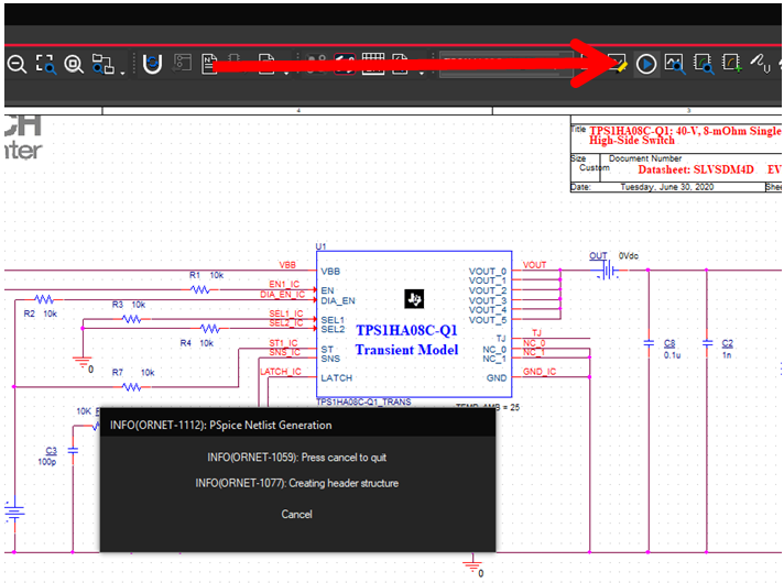
Once the schematic and operation of the device is correct based on desired behavior and load, the simulation can be run. Before running the default simulation profile, ensure that the simulation profile is configured correctly.
The simulation profile can be edited by selecting Edit Simulation Profile in the drop-down menu that appears when selecting PSPICE on the main toolbar. A window such as the one shown in Figure 2-5 appears.
 Figure 2-5 Running a Simulation in
PSpice
Figure 2-5 Running a Simulation in
PSpiceOnce the appropriate settings have been configured, select the OK button. Running the simulation is done by selecting the RUN button on the main bar or clicking the F5 key.