SLUUCO2 August   2022 TPSM8D6B24


  1.   Abstract
  2.   Trademarks
  3. Description
    1. 1.1 Before You Begin
    2. 1.2 Features
  4. Electrical Performance Specifications
  5. Schematic
  6. Test Setup
    1. 4.1 Test and Configuration Software
      1. 4.1.1 Description
      2. 4.1.2 Features
    2. 4.2 Test Equipment
      1. 4.2.1 Voltage Source
      2. 4.2.2 Oscilloscope
      3. 4.2.3 Multimeters
      4. 4.2.4 Output Load
      5. 4.2.5 Fan
      6. 4.2.6 USB-to-GPIO Interface Adapter
      7. 4.2.7 Recommended Wire Gauge
    3. 4.3 List of Test Points, Jumpers, and Connectors
    4. 4.4 Evaluating Split Rail Input
  7. EVM Configuration Using the Fusion GUI
    1. 5.1 Configuration Procedure
  8. Test Procedure
    1. 6.1 Line and Load Regulation and Efficiency Measurement Procedure
    2. 6.2 Efficiency Measurement Test Points
    3. 6.3 Control Loop Gain and Phase Measurement Procedure
  9. Performance Data and Typical Characteristic Curves
    1. 7.1 Efficiency
    2. 7.2 Load Regulation
    3. 7.3 Line Regulation
    4. 7.4 Transient Response
    5. 7.5 Control Loop Bode Plot
    6. 7.6 Output Ripple
    7. 7.7 Control On
    8. 7.8 Control Off
    9. 7.9 Thermal Image
  10. EVM Assembly Drawing and PCB Layout
  11. Bill of Materials
  12. 10Using the Fusion GUI
    1. 10.1  Opening the Fusion GUI
    2. 10.2  General Settings
    3. 10.3  Changing ON_OFF_CONFIG
    4. 10.4  Pop-Up for Some Commands While Conversion is Enabled
    5. 10.5  SMBALERT# Mask
    6. 10.6  Device Info
    7. 10.7  Phase Commands
    8. 10.8  All Config
    9. 10.9  Pin Strapping
    10. 10.10 Monitor
    11. 10.11 Status

Monitor

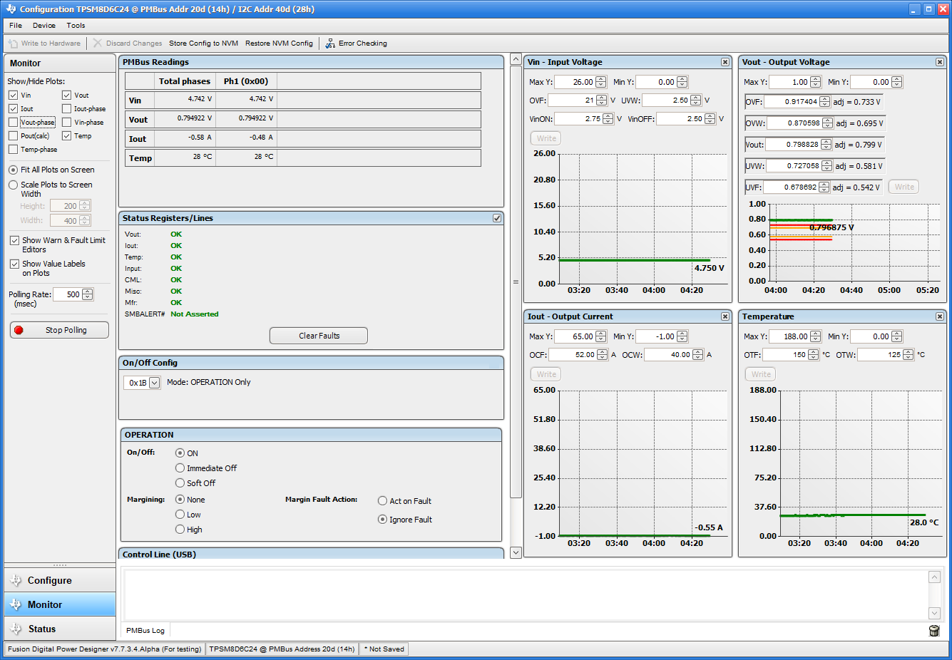
When the Monitor screen (Figure 10-10) is selected, the screen changes to display real-time data of the parameters that are measured by the device. This screen provides access to:

  • Graphs of Vout, Iout, Vin, Pout, and Temperature
  • Start and Stop Polling, which turns ON or OFF the real-time display of data
  • Quick access to On/Off Config
  • Control pin activation and OPERATION command
  • Margin control
  • Clear Fault: Selecting Clear Faults clears any prior fault flags.

With two devices stacked together, the Iout reading is the total load supported by both devices. Iout also shows the current in each phase.
GUID-895CE883-01F5-43FB-BDBF-0FDF2D63BF67-low.pngFigure 10-10 Monitor Screen