SLUAAG7 October 2021 BQ25720
- Trademarks
- 1Introduction
-
2Design Considerations for Notebook
Applications
- 2.1 Vmin Active Protection (VAP)
- 2.2 Fast Role Swap (FRS)
- 2.3 Processor Hot Indication
- 2.4 Two-Level Battery Discharge Current Limit
- 2.5 Pass Through Mode (PTM) Operation
- 2.6 Seamless Mode Transition
- 2.7 Current and Power Monitor
- 2.8 Input Source Dynamic Power Management
- 2.9 Power Up USB Port From Battery (USB OTG)
- 3Test Results
- 4Summary
- 5References
1.2 Type-C Battery Charging Topologies
The main challenge in the power delivery architecture is how to use 5 V-20 V adapter voltage to charge a 3 V to approximately 16.8 V battery (from 1 cell battery completely discharged to 4 cells battery full charged). In most cases, the input voltage range can vary from below the battery voltage to above the battery voltage. Figure 1-2, Figure 1-3, and Figure 1-4 list three common topologies for Type-C charging.
 Figure 1-2 Pre-Boost Topology
The first way is to use a pre-boost topology, as shown in Figure 1-2. This approach boosts USB adapter voltage to a level higher than the highest USB adapter voltage (>20 V) and then uses a buck charger to charge the battery. The additional boost converter provide a stable high voltage to buck charger, however additional circuit increases total solution cost and board size, and reduces the overall efficiency due to the additional power loss in the boost converter.
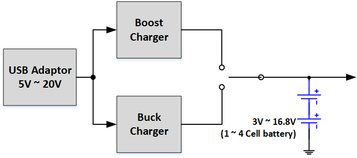
 Figure 1-3 Buck Charger + Boost Charger
Topology
Figure 1-3 Buck Charger + Boost Charger
TopologyFigure 1-3 shows a topology using either buck charger or boost charger. It needs to monitor input voltage and output voltage, and automatically select buck charger or boost charger. This topology could eliminate the additional power loss in the pre-boost approach, however, still requires an additional boost charger, which increases total solution cost.
 Figure 1-4 Buck-Boost Charger
Topology
Figure 1-4 Buck-Boost Charger
TopologyThe buck-boost charger topology has become increasingly popular, which is shown in Figure 1-4. Buck-boost charger is able to charge a battery from nearly any source, regardless of whether the input voltage is higher or lower than the battery voltage. It could achieve a better design with the smallest solution size and the best overall efficiency.