SLOA227B October 2015 – March 2019 TRF7964A , TRF7964A , TRF7970A , TRF7970A
-
NFC/HF RFID reader/writer using the TRF7970A
- Trademarks
- 1 Terms, Definitions, and Symbols
- 2 Introduction
- 3 Initial RF Collision
- 4 TRF7970A Register Settings
- 5 Reader/Writer Mode
- 6 Hardware Description
- 7 Reader/Writer Firmware Example
- 8 Quick Start Guide
- 9 Operational Overview
- 10 Reader/Writer Interoperability Results
- 11 Conclusion
- 12 References
- Revision History
9 Operational Overview
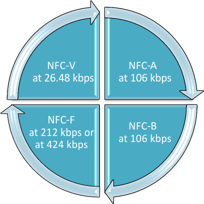
The reader/writer demo on the MSP430F5529 has two modes: a stand-alone mode and a host mode that requires a system (PC typically) to run the TI NFC Tool GUI. The stand-alone mode can be configured for specific bit rates for each supported tag technology: Type 2 and Type 4A at 106, 212, 424, or 848 kbps, Type 3 at 212 or 424 kbps, Type 4B at 106, 212, 424, or 848 kbps, and Type 5 at 26.48 kbps.
The order in which the firmware polls for the different tag technologies is NFC-A (Type 2 or Type 4A), NFC-B (Type 4B), NFC-F (Type 3), and NFC-V (Type 5). If no tags are detected, the polling returns to NFC-A (Type 2 or Type 4A) (see Figure 27 for the switching mechanism while in stand-alone mode). Polling commands for NFC-A and NFC-B must be sent at 106 kbps, and then the bit rate can be increased after activation is completed.
 Figure 27. Reader/Writer Tag Polling Mechanism
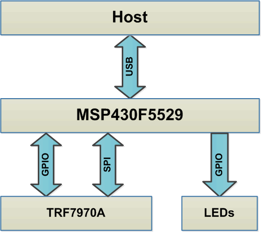
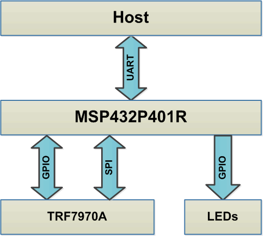
 The second mode requires a host (PC) to run the TI NFC Tool GUI and then connect to either the MSP430F5529 Experimenter Board or LaunchPad development kit through the USB CDC (see Figure 28), or the MSP432P401R LaunchPad development kit through the back channel UART interface (see Figure 29). The GUI allows the user to select which modes to enable/disable. When a connection is established with an NFC-enabled device, the GUI switches to the reader/writer tab, which allows the user to view the tag data and send a customized text or URI RTD for NDEF formatted tags.
 Figure 28. Reader/Writer Demo System Block Diagram for MSP430F5529
  Figure 29. Reader/Writer Demo System Block Diagram for MSP432P401