SLOA227B October 2015 – March 2019 TRF7964A , TRF7964A , TRF7970A , TRF7970A
-
NFC/HF RFID reader/writer using the TRF7970A
- Trademarks
- 1 Terms, Definitions, and Symbols
- 2 Introduction
- 3 Initial RF Collision
- 4 TRF7970A Register Settings
- 5 Reader/Writer Mode
- 6 Hardware Description
- 7 Reader/Writer Firmware Example
- 8 Quick Start Guide
- 9 Operational Overview
- 10 Reader/Writer Interoperability Results
- 11 Conclusion
- 12 References
- Revision History
2 Introduction
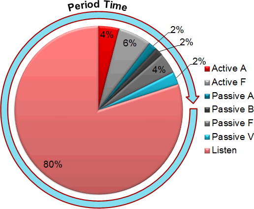
The TRF7970A device supports three modes: reader/writer, card emulation, and peer-to-peer. This document describes how to use the TRF7970A in reader/writer mode. This mode allows an NFC enabled system to activate and read existing RFID and NFC tags. In the case of the TRF7970A, it is possible to read Type 2 (T2T), Type 3 (T3T), Type 4A or B (T4T), and ISO15693 (T5T) tag platforms. NFC transceivers supporting reader/writer mode typically poll to check if a tag or NFC peer is present every 500 ms. This time is known as the period time, which includes the time the transceiver is polling (searching for a tag) plus the time the transceiver is listening to be activated (in the case it is emulating a tag or is in peer-to-peer target mode). In Figure 1, for example, the transceiver is first polling for Active A and F technology (active peer-to-peer). Next, it polls for passive A technology (ISO14443A-3), passive B (ISO14443B-3), passive F (ISO18092), and then passive V (ISO15693).
For more information on active peer-to-peer communication and how passive A and F technology can be used to activate peer-to-peer communication, see NFC active and passive peer-to-peer communication using the TRF7970A.
 Figure 1. NFC Transceiver Polling Sequence Example
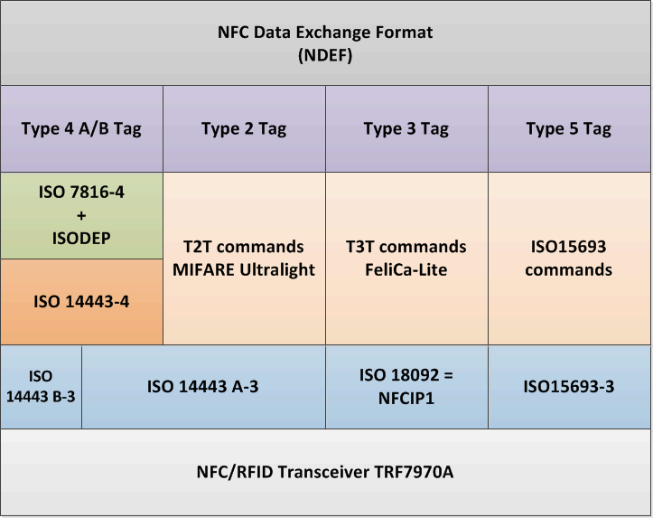
 The reader always generates the RF field and the tag load modulates the RF field to send their response. Figure 2 shows the NFC/RFID layers used to read and write tags. Both T2T and T4TAplatforms use technology ISO14443-3 (Type A) at an initial bit rate of 106 kbps for tag activation. T4TB platforms use technology ISO14443-3 (Type B) at an initial bit rate of 106 kbps for tag activation. After the activation process is completed, both T4TA and T4TB platforms use ISO7816-4 and ISODEP layers to read or write the tag content. After the T2T platform is activated it uses T2T commands to read or write the tag content. T3T platforms use technology ISO18092 at an initial bit rate of 212 kbps or 424 kbps for tag activation. When the T3T is activated it uses T3T commands to read or write the tag content. T5T platforms use technology ISO15693 for activation and to read the tag content.
 Figure 2. Reader/Writer Layers Including the PHY (TRF7970A)
 A 16-bit and a 32-bit microcontroller were used to interface with the TRF7970A to demonstrate a reference example of the reader/writer mode. The firmware supports flexible functions that allow the user to enable or disable reading T2T, T3T, T4TA/B, and T5T platforms. Additionally, the firmware provides support for NFC-enabled smart phones that can emulate tag platforms. The firmware can activate and select NFC-enabled smart phones, allowing users to read card data by creating their own custom applications using existing APIs.
Table 1 lists the NFC/RFID technologies that the provided example firmware supports.
NOTE
Type 1 tags are not ISO compliant and require the use of Direct Mode 0 (DM0) to receive raw RF packets. Due to this, the firmware example does not support these tags.
Table 1. NFC/RFID Tags Supported by Reader/Writer Mode
| Tag Technology | Support |
|---|---|
| Type 1 | ✗ |
| Type 2 | ✓ |
| Type 3 | ✓ |
| Type 4A | ✓ |
| Type 4B | ✓ |
| Type 5 | ✓ |