SLOA227B October 2015 – March 2019 TRF7964A , TRF7964A , TRF7970A , TRF7970A
-
NFC/HF RFID reader/writer using the TRF7970A
- Trademarks
- 1 Terms, Definitions, and Symbols
- 2 Introduction
- 3 Initial RF Collision
- 4 TRF7970A Register Settings
- 5 Reader/Writer Mode
- 6 Hardware Description
- 7 Reader/Writer Firmware Example
- 8 Quick Start Guide
- 9 Operational Overview
- 10 Reader/Writer Interoperability Results
- 11 Conclusion
- 12 References
- Revision History
3 Initial RF Collision
NFC enabled systems can support both reader/writer mode and listen mode. To ensure that two NFC reader devices do not send commands at the same time, an initial RF collision detection is required. The transceiver must check the external received signal strength indicator (RSSI) value that measures the strength of the demodulated subcarrier signal before enabling its own RF field. If the RSSI value is greater than 0x00, it will not enable its RF field.
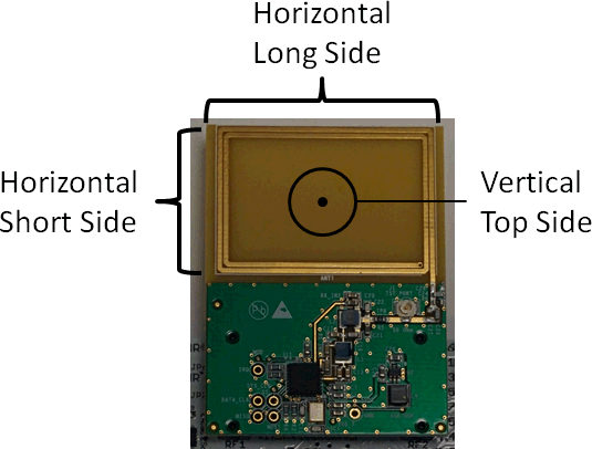
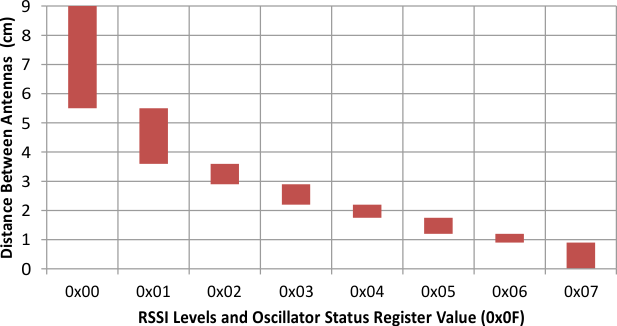
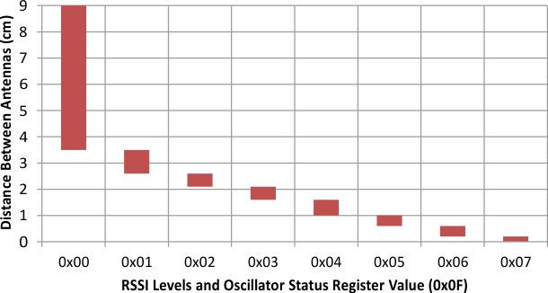
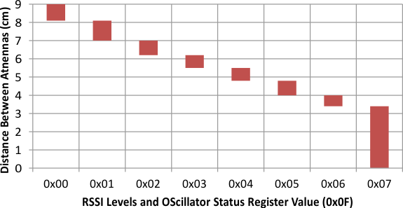
The relation between the 3-bit code and the external RF field strength (A/m) sensed by the antenna must be determined by calculation or by experiments for each antenna design. The antenna Q-factor, coupling factor between the two antennas and connection to the RF input influence the result. Figure 4 through Figure 6 provide the correlation of the free space distance between two unmodified TRF7970ATB modules and the 3-bit external RSSI value in three directions (see Figure 3 for more details on each orientation). One TRF7970A has its RF field at full power (+5 V), and the second TRF7970A is used to take RSSI measurements across different distances.
 Figure 3. RSSI Level Measurement Orientations
  Figure 4. Long Side RSSI Level Measurement
  Figure 5. Short Side RSSI Level Measurement
  Figure 6. Top Side RSSI Level Measurement
 The initial RF collision can be accomplished by performing the following steps:
- Write a 0x02 or 0x03 (3-V or 5-V operation) to the Chip Status Control register (0x00), disabling the transmitter and enabling the receiver.
- Send a Test External RF direct command (0x19).
- Delay 50 µs to allow the transceiver to measure the field strength and latch the value into the RSSI register.
- Read the RSSI Levels and Oscillator Status register (0x0F).
- If the active channel RSSI value (bits 2-0) is greater than 0, remain in target mode for a predetermined n milliseconds.
- If the active channel RSSI value (bits 2-0) is equal to 0, go into initiator or target mode for active or passive communication.