• Menu
  • Product
  • Email
  • PDF
  • Order now
  • NFC/HF RFID reader/writer using the TRF7970A

    • SLOA227B October   2015  – March 2019 TRF7964A , TRF7964A , TRF7970A , TRF7970A


  • CONTENTS
  • SEARCH
  • NFC/HF RFID reader/writer using the TRF7970A
  1.   NFC/HF RFID reader/writer using the TRF7970A
    1.     Trademarks
    2. 1  Terms, Definitions, and Symbols
    3. 2  Introduction
    4. 3  Initial RF Collision
    5. 4  TRF7970A Register Settings
    6. 5  Reader/Writer Mode
      1. 5.1 Technology Activation Using the TRF7970A
        1. 5.1.1 ISO14443-3 Type A (Type 2 and Type 4A Tags)
          1. 5.1.1.1 Additional Tag Activation Commands for Type 4A Tags
        2. 5.1.2 ISO14443B-3 (Type 4B Tags)
          1. 5.1.2.1 Selection for Type 4B Tags
        3. 5.1.3 ISO18092 (Type 3 Tags)
        4. 5.1.4 ISO15693 (Type 5 Tags)
      2. 5.2 Tag Memory Format With NDEF Examples
        1. 5.2.1 Type 2 Tags
          1. 5.2.1.1 Layout
          2. 5.2.1.2 NDEF Format
            1. 5.2.1.2.1 Static Memory Structure
            2. 5.2.1.2.2 Dynamic Memory Structure
          3. 5.2.1.3 Capability Container
        2. 5.2.2 Type 3 Tags
          1. 5.2.2.1 Layout
          2. 5.2.2.2 NDEF Format
          3. 5.2.2.3 Attribute Information Block
        3. 5.2.3 Type 4 Tags
          1. 5.2.3.1 Layout
          2. 5.2.3.2 NDEF Format
          3. 5.2.3.3 Capability Container
        4. 5.2.4 Type 5 Tags
          1. 5.2.4.1 Layout
          2. 5.2.4.2 NDEF Format
          3. 5.2.4.3 Capability Container
    7. 6  Hardware Description
      1. 6.1 LaunchPad™ Development Kit and BoosterPack™ Plug-in Module Setup
        1. 6.1.1 BoosterPack Plug-in Module: DLP-7970ABP
        2. 6.1.2 LaunchPad Development Kit: MSP-EXP430F5529LP
        3. 6.1.3 LaunchPad Development Kit: MSP-EXP432P401R
      2. 6.2 Bundle Available for Purchase
    8. 7  Reader/Writer Firmware Example
      1. 7.1 Reader/Writer APIs
      2. 7.2 Implementing a Reader/Writer Sample Application
        1. 7.2.1 Low-Level Initialization
          1.        Example 1. MCU and TRF7970A Initialization Code Snippet
        2. 7.2.2 Reader/Writer NFC Stack Configuration
          1.        Example 2. Reader/Writer Stack Configuration Code Snippet
        3. 7.2.3 Activation
        4. 7.2.4 Reading and Writing Tags
    9. 8  Quick Start Guide
    10. 9  Operational Overview
    11. 10 Reader/Writer Interoperability Results
    12. 11 Conclusion
    13. 12 References
  2.   Revision History
  3. IMPORTANT NOTICE
search No matches found.
  • Full reading width
    • Full reading width
    • Comfortable reading width
    • Expanded reading width
  • Card for each section
  • Card with all content


APPLICATION NOTE

NFC/HF RFID reader/writer using the TRF7970A

NFC/HF RFID reader/writer using the TRF7970A

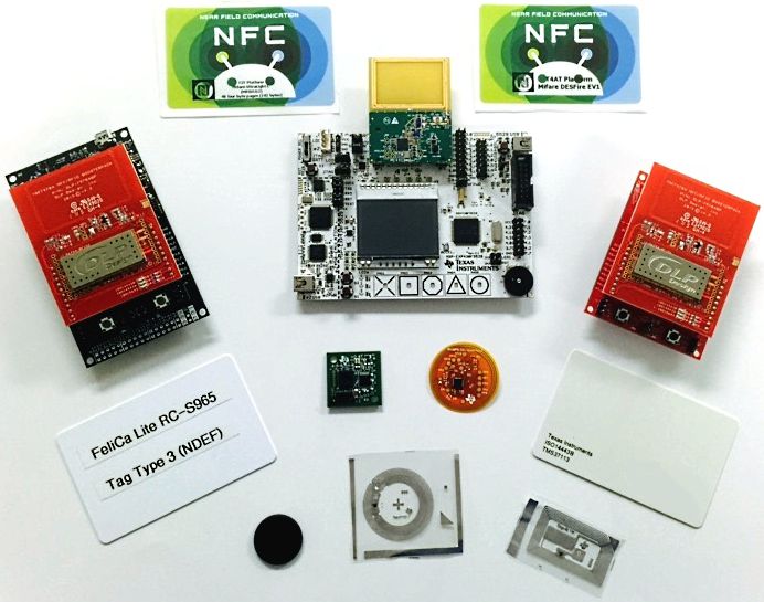
The Near Field Communication (NFC) market is emerging into multiple fields including medical, consumer, retail, industrial, automotive, and smart grid. Reader/Writer is one of the three operational modes supported by the TRF7970A. When using reader/writer mode the user can configure the TRF7970A to read Type 2, Type 3, Type 4A, Type 4B, and Type 5 tag platforms, also called transponders. The tags can store NFC Data Exchange Format (NDEF) messages or proprietary defined data.

This application report describes the fundamental concepts of reader/writer mode and how to properly configure the TRF7907A transceiver for each supported technology. Furthermore, it describes how to successfully activate, select, and read or write supported tags.

This application report and example firmware focuses on examples where the user presents only one tag at a time. However, it is possible from both a hardware and firmware standpoint to read multiple tags at the same time.

For applications that use only reader/writer mode, the TRF7964A can be used as a drop-in alternative to the TRF7970A.

Sample code described in this document can downloaded from http://www.ti.com/lit/zip/sloa227.

abstract_photo.jpg

Trademarks

BoosterPack, LaunchPad are registered trademarks of Texas Instruments.

Arm, Cortex are registered trademarks of Arm Limited.

All other trademarks are the property of their respective owners.

1 Terms, Definitions, and Symbols

ALL_REQ
NFC-A Polling command, equivalent to ISO14443-3 short frame command WupA (0x52)

ALLB_REQ
NFC-B Polling command, equivalent to ISO14443-3 command WupB

APDU
Application Protocol Data Unit, used in command-response pairs to exchange I (information), R (receive ready) or S (supervisory) blocks.

ATTRIB
PICC Selection Command, Type B

ATQA
Answer To ReQuest A, ISO14443-3 term, equivalent to NFC term SENS_RES

ATQB
Answer To ReQuest B, ISO14443-3 term, equivalent to NFC term SENSB_RES

CC
Capability Container, contains management data and is stored inside a read-only EF. This EF is located inside the NDEF tag application. Default (or basic) file ID for this file (for NFC) is 0xE103. See NFC Type 4 tag Operation Specification and ISO/IEC 7816-4 for more information.

CE
Card Emulation, one of the three modes offered by NFC devices. In this optional mode of NFC operation, an NFC Forum device is considered to be a card emulation platform only when it is emulating a Type 3, Type 4A or Type 4B tag platform. Emulation of any other cards or tags is outside the scope of the NFC Forum Brand Promise.

DEP
Data Exchange Protocol, an abstracted operational layer that is using either ISO or NFC protocols to exchange data. Thus, two terms can be created with this acronym: ISO-DEP and NFC-DEP. In the context of this document, after activation and selection of the emulated card and before deactivation, ISO-DEP is used exclusively to exchange data between reader/writer (PCD) and tag platform (PICC).

EF
Elementary File, a set of data objects, records or units sharing the same file identifier and the same security attributes

File Identifier
Two byte data element used to address a file

fc
Carrier frequency, in the context of NFC/HF RFID, is 13.56 MHz ±7 kHz. This is the fundamental transmit frequency of the reader/writer (also called PCD)

Initiator
Generator of the RF field and source of the beginning of the NFCIP-1 communication

MIME
Multipurpose Internet Mail Extensions

Modulation Index, m
Signal amplitude ratio of eq_modulation_index_sloa227.gif, where b is the ratio between the modulated amplitude and the initial signal amplitude. The index m is defined per protocol type for both downlink and uplink and is generally expressed as a percentage (for example, Type A uses m = 100%, and Type B uses m = 8 to 14%).

NDEF
NFC Data Exchange Format

NFC
Near Field Communication

PCB
Protocol Control Byte, used for conveying information required to control data transmission of blocks during the exchange of command-response APDU pairs. Bit coding of this byte and use rules are found in ISO/IEC FDIS 14443-4.

PCD
Proximity Coupling Device (also commonly referred to as reader/writer)

PICC
Proximity Integrated Circuit Card (also commonly referred to as tag, tag platform or transponder)

PUPI
Pseudo Unique PICC Identifier (randomly generated or static number returned by PICC as part of the response to REQB, WupB, ALLB_REQ or SENSB_REQ)

RTD
Record Type Definition

SAK
Select AcKnowledge (from ISO14443-3), in NFC terms this is also called SEL_RES

SDD_RES
Equivalent to ISO14443-3 response to SDD_REQ, and is complete NFCID1 CLn + BCC (if cascade level 1 (single size UID) or indicates NFCID1 is incomplete in the response and further cascade levels must be completed to obtain complete NFCID1+BCC.

SDD_REQ
Equivalent to ISO14443-3 Type A anticollision sequence. Comprised of SEL_CMD, SEL_PAR and n data bits coded based on cascade level specified by SEL_CMD and calculated by value of SEL_PAR

SEL_RES
Equivalent to ISO14443-3 SAK response

SENS_REQ
NFC-A Polling command, equivalent to ISO14443-3 short frame command REQ_A (0x26)

SENS_RES
NFC-A Polling Response, equivalent to ISO14443-3 ATQA

SENSB_REQ
NFC-B Polling command, equivalent to ISO14443-3 command REQ_B

SENSB_RES
NFC-B Polling command response, equivalent to ISO14443-3 ATQB

SENSF_REQ
NFC-F Polling command

SENSF_RES
NFC-F Polling response

Single Device Detection (SDD)
Algorithm used by the reader/writer to detect one out of several targets in its RF field (Type A anticollision, from ISO/IEC 14443-3)

T2T
Type 2Tag

T3T
Type 3Tag

T4T
Type 4Tag

T5T
Type 5Tag

Tag
See Tag Platform

Tag Platform
Responds to reader/writer (PCD) commands by using load modulation scheme (passive operation)

Throughout this document, the terms tag, tag platform, and transponder all have the same meaning.

TLV
Type Length Value

Transponder
See Tag Platform

UID
Unique IDentifier

VICC
Vicinity Integrated Circuit Card

2 Introduction

The TRF7970A device supports three modes: reader/writer, card emulation, and peer-to-peer. This document describes how to use the TRF7970A in reader/writer mode. This mode allows an NFC enabled system to activate and read existing RFID and NFC tags. In the case of the TRF7970A, it is possible to read Type 2 (T2T), Type 3 (T3T), Type 4A or B (T4T), and ISO15693 (T5T) tag platforms. NFC transceivers supporting reader/writer mode typically poll to check if a tag or NFC peer is present every 500 ms. This time is known as the period time, which includes the time the transceiver is polling (searching for a tag) plus the time the transceiver is listening to be activated (in the case it is emulating a tag or is in peer-to-peer target mode). In Figure 1, for example, the transceiver is first polling for Active A and F technology (active peer-to-peer). Next, it polls for passive A technology (ISO14443A-3), passive B (ISO14443B-3), passive F (ISO18092), and then passive V (ISO15693).

For more information on active peer-to-peer communication and how passive A and F technology can be used to activate peer-to-peer communication, see NFC active and passive peer-to-peer communication using the TRF7970A.

fig01_NFC_Transceiver_Polling.pngFigure 1. NFC Transceiver Polling Sequence Example

The reader always generates the RF field and the tag load modulates the RF field to send their response. Figure 2 shows the NFC/RFID layers used to read and write tags. Both T2T and T4TAplatforms use technology ISO14443-3 (Type A) at an initial bit rate of 106 kbps for tag activation. T4TB platforms use technology ISO14443-3 (Type B) at an initial bit rate of 106 kbps for tag activation. After the activation process is completed, both T4TA and T4TB platforms use ISO7816-4 and ISODEP layers to read or write the tag content. After the T2T platform is activated it uses T2T commands to read or write the tag content. T3T platforms use technology ISO18092 at an initial bit rate of 212 kbps or 424 kbps for tag activation. When the T3T is activated it uses T3T commands to read or write the tag content. T5T platforms use technology ISO15693 for activation and to read the tag content.

fig02_RW_Layers_Incl_PHY.gifFigure 2. Reader/Writer Layers Including the PHY (TRF7970A)

A 16-bit and a 32-bit microcontroller were used to interface with the TRF7970A to demonstrate a reference example of the reader/writer mode. The firmware supports flexible functions that allow the user to enable or disable reading T2T, T3T, T4TA/B, and T5T platforms. Additionally, the firmware provides support for NFC-enabled smart phones that can emulate tag platforms. The firmware can activate and select NFC-enabled smart phones, allowing users to read card data by creating their own custom applications using existing APIs.

Table 1 lists the NFC/RFID technologies that the provided example firmware supports.

NOTE

Type 1 tags are not ISO compliant and require the use of Direct Mode 0 (DM0) to receive raw RF packets. Due to this, the firmware example does not support these tags.

Table 1. NFC/RFID Tags Supported by Reader/Writer Mode

Tag Technology Support
Type 1 ✗
Type 2 ✓
Type 3 ✓
Type 4A ✓
Type 4B ✓
Type 5 ✓

3 Initial RF Collision

NFC enabled systems can support both reader/writer mode and listen mode. To ensure that two NFC reader devices do not send commands at the same time, an initial RF collision detection is required. The transceiver must check the external received signal strength indicator (RSSI) value that measures the strength of the demodulated subcarrier signal before enabling its own RF field. If the RSSI value is greater than 0x00, it will not enable its RF field.

The relation between the 3-bit code and the external RF field strength (A/m) sensed by the antenna must be determined by calculation or by experiments for each antenna design. The antenna Q-factor, coupling factor between the two antennas and connection to the RF input influence the result. Figure 4 through Figure 6 provide the correlation of the free space distance between two unmodified TRF7970ATB modules and the 3-bit external RSSI value in three directions (see Figure 3 for more details on each orientation). One TRF7970A has its RF field at full power (+5 V), and the second TRF7970A is used to take RSSI measurements across different distances.

fig03_RSSI_Level_Measur_Orient.pngFigure 3. RSSI Level Measurement Orientations
fig04_Long_Side_RSSI.gifFigure 4. Long Side RSSI Level Measurement
fig05_Short_Side_RSSI.gifFigure 5. Short Side RSSI Level Measurement
fig06_Top_Side_RSSI.gifFigure 6. Top Side RSSI Level Measurement

The initial RF collision can be accomplished by performing the following steps:

  1. Write a 0x02 or 0x03 (3-V or 5-V operation) to the Chip Status Control register (0x00), disabling the transmitter and enabling the receiver.
  2. Send a Test External RF direct command (0x19).
  3. Delay 50 µs to allow the transceiver to measure the field strength and latch the value into the RSSI register.
  4. Read the RSSI Levels and Oscillator Status register (0x0F).
  5. If the active channel RSSI value (bits 2-0) is greater than 0, remain in target mode for a predetermined n milliseconds.
  6. If the active channel RSSI value (bits 2-0) is equal to 0, go into initiator or target mode for active or passive communication.

4 TRF7970A Register Settings

After powering up the TRF7970A, sending SOFT_INIT (0x03) and IDLE (0x00) direct commands enables the passive target mode at 106 kbps. Table 2 lists the default value of registers 0x00 to 0x16 and 0x18h to 0x1C after the commands are issued. Furthermore, it shows the registers that must be modified from their default values for reader/writer mode.

The ISO Control (0x01) register is modified whenever the reader/writer technology or bit rate changes. The Chip Status Control (0x00) register is modified after initialization, and whenever the RF field is enabled or disabled. The Special Function (0x10) register requires modification for writing to Type 2 tags. The Modulator and SYS_CLK Control (0x09), RX Special Settings (0x0A), and Regulator and I/O Control (0x0B) registers need to be modified only once, after initialization. The NFC Target Detection Level register must be modified after initialization based on the TRF7970A silicon errata.

Table 2. TRF7970A Default Register Values After SOFT_INIT and IDLE Direct Commands

Address Register Value Requires Modification
0x00 Chip Status Control 0x01 Yes
0x01 ISO Control 0x21 Yes
0x02 ISO14443B TX options 0x00 No
0x03 ISO14443A high bit rate options 0x00 No
0x04 TX timer setting, H-byte 0xC1 No
0x05 TX timer setting, L-byte 0xC1 No
0x06 TX pulse-length control 0x00 No
0x07 RX no response wait 0x0E No
0x08 RX wait time 0x07 No
0x09 Modulator and SYS_CLK control 0x91 Yes
0x0A RX Special Setting 0x10 Yes
0x0B Regulator and I/O control 0x87 Yes
0x0C IRQ status 0x00 No
0x0D Collision position and interrupt mask 0x3E No
0x0E Collision position 0x00 No
0x0F RSSI levels and oscillator status 0x40 No
0x10 Special Function 0x00 Yes
0x11 Special Function 0x00 No
0x12 RAM 0x00 No
0x13 RAM 0x00 No
0x14 Adjustable FIFO IRQ Levels 0x00 Optional
0x15 Reserved 0x00 No
0x16 NFC Low Field Detection Level 0x00 No
0x18 NFC Target Detection Level 0x00 Yes
0x19 NFC Target Protocol 0x00 No
0x1A Test 0x00 No
0x1B Test 0x00 No
0x1C FIFO status 0x00 No

5 Reader/Writer Mode

The TRF7970A supports reader/writer mode for NFC-A (Type 2/4A), NFC-B (Type 4B), NFC-F (Type 3), and NFC-V (Type 5) tag platforms. Only one technology can be activated at a time, requiring the reader/writer mode to poll through each technology individually to detect NFC tags. The way this is handled in the example firmware is illustrated by the flow diagram presented in Figure 7.

After the initial RF collision is completed and the RF field is turned on, there is a guard time before polling for the first technology. The guard time is a specified period of time where the RF field is on, but is unmodulated. The guard time allows for a tag platform to have enough time to be ready to reply to commands that are issued. The guard time requirements vary with each technology, and therefore the ISO specifications for an individual technology should be referenced to find out more information about the guard time for that technology.

For the TRF7970A, there must be a 0x20 or 0x21 written to the Chip Status Control (0x00) register, and the appropriate technology setup for the ISO Control (0x01) register. The example firmware provided implements longer guard times than the minimum required by the specifications for NFC-A and NFC-B. This is done to improve the performance of systems that rely on an RF field to power up additional devices.

The flow diagram for example firmware in Figure 7 does not explicitly show the guard times, but they occur before sending the initial polling command for each technology. For example, the guard time before sending an ALL_REQ or SENS_REQ is set to be 5 ms in the firmware, so if the firmware confirms that NFC-A is enabled, the firmware then turns on the RF field and waits for 5 ms before issuing the ALL_REQ or SENS_REQ command.

The firmware has been structured based on the NFC Forum Activity 1.0 specification, and does not include any anticollision processes for detecting and selecting multiple tags of the same technology. This is equivalent to having the device connection limit set to zero.

It is possible to implement such processes with the TRF7970A by modifying the provided example firmware to support anticollision processes for the different technologies. The firmware has been designed to promote flexibility for modifications as well as custom applications, and the existing APIs can be leveraged to add anticollision functionality for each technology.

fig07_RW_Flow_Diagram.gifFigure 7. TRF7970A Reader/Writer Flow Diagram


Texas Instruments

© Copyright 1995-2025 Texas Instruments Incorporated. All rights reserved.
Submit documentation feedback | IMPORTANT NOTICE | Trademarks | Privacy policy | Cookie policy | Terms of use | Terms of sale