SLOA192B April 2014 – March 2019 TRF7970A , TRF7970A
-
NFC active and passive peer-to-peer communication using the TRF7970A
- Trademarks
- 1 Introduction
- 2 Initial RF Collision
- 3 TRF7970A Register Settings
- 4 Peer-to-Peer at 106 kbps
- 5 Peer-to-Peer at 212 kbps and 424 kbps
- 6 Hardware Description
- 7 Passive and Active Peer-to-Peer Firmware Example
- 8 Quick Start Guide
- 9 Operational Overview
- 10 Peer-to-Peer Interoperability Results
- 11 Conclusion
- 12 References
- Revision History
9 Operational Overview
The peer-to-peer demo on the MSP430F5529 has two modes. The first mode is a stand-alone mode where both initiator and target are enabled for passive supporting 106 kbps, 212 kbps and 424 kbps. The firmware sends polling commands for NFC-A Passive at 106 kbps and NFC-F passive at 212 kbps each time the initiator mode is enabled. If all the polling commands timeout, the peer-to-peer stack switches the mode to target mode. In target mode, the firmware waits for a technology to be activated for 500 ms. If no technology is activated during target mode, the firmware switches the mode to initiator mode. When a connection is established with an NFC-enabled device, press the button S1 to send a Text RTD or press the button S2 to send a MIME RTD (TI Logo).
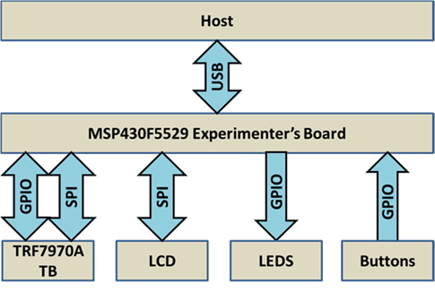
The second mode requires a host (PC) to run the TI NFC Tool and connect to the MSP430F5529 through the USB CDC. Figure 17 shows the system block diagram. When the GUI is connected to the MSP430F5529, pressing the buttons S1 or S2 will not send an NDEF as it previously did in stand-alone mode. The GUI allows you to select which modes to enable and disable. Once a connection is established with an NFC-enabled device, the GUI switches to the peer-to-peer tab, which allows you to send a modifiable Text or URI RTD.
 Figure 17. Peer-to-Peer Demo System Block Diagram