Peer-to-peer (P2P) is one of the three modes supported by the TRF7970A. The Near Field Communication (NFC) market is emerging into multiple fields including medical, consumer, retail, industrial, automotive, and smart grid. P2P is very common in these fields, because it allows for a wireless virtual channel to be created between two devices. This application report describes two NFC technologies, the NFC-F and NFC-A protocols, which are used to initiate the communication for peer-to-peer active or passive modes. Furthermore, this application report explains how to implement an application using active or passive P2P communication, supporting baud rates of 106 kbps, 212 kbps and 424 kbps on the TRF7970A transceiver.
Project collateral and source code discussed in this application report can be downloaded from http://www.ti.com/lit/zip/sloa192.
BoosterPack, LaunchPad are registered trademarks of Texas Instruments.
FeliCa is a registered trademark of Sony Corporation.
All other trademarks are the property of their respective owners.
The TRF7970A supports three modes: reader/writer, card emulation, and peer-to-peer. This document describes how to use the TRF7970A in peer-to-peer (P2P) active or passive. P2P requires two NFC-enabled devices to communicate using technologies NFC-A or NFC-F at baud rates of 106 kbps (NFC-A), 212 kbps (NFC-F), or 424 kbps (NFC-F). The transceiver that is initially polling and initiates the communication is the initiator. The transceiver that is initially listening is the target.
The initiator always generates the RF field for both active and passive communication modes. However, the target generates its own RF field only for active mode (while the initiator's RF field is disabled) and load modulates the initiator's RF field in passive mode. After the technology selection for either mode has been completed, the higher layers are the same (as shown in Figure 1). The NDEF Push Protocol (NPP) was commonly used on Gingerbread Android NFC devices as the protocol to push NDEF messages from one NFC device to another; however, the Simple NDEF Exchange Protocol (SNEP) has become the standard on Ice Cream Sandwich Android NFC devices and onward.
A 16-bit and a 32-bit microcontroller are used to interface with the TRF7970A to demonstrate a reference example of the peer-to-peer mode. The firmware supports flexible functions that let the user enable or disable different peer-to-peer modes and technologies. The firmware supports both initiator and target for active and passive communication at baud rates of 106 kbps, 212 kbps, and 424 kbps. Additionally, the firmware can send and receive NDEF messages from NFC-enabled smart phones with SNEP.
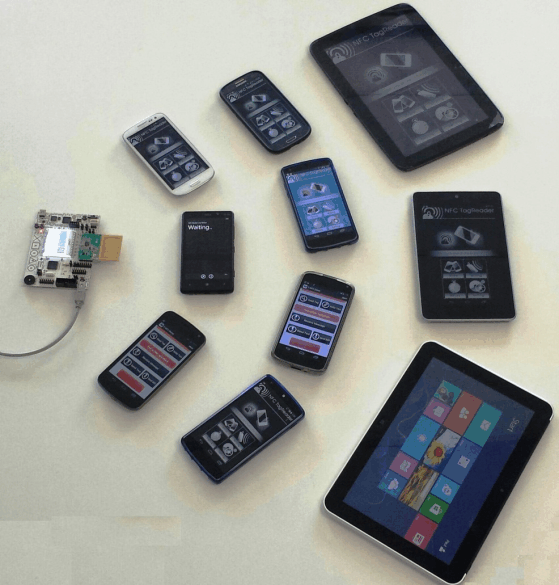
Table 1 lists the NFC-enabled devices used to validate the firmware.
Smartphone Model (Release Date) | Operating System | Kernel Version |
---|---|---|
Samsung Galaxy Nexus (Nov 2011) | Android 4.3 | 3.0.72 Jun 7 2013 |
Samsung Galaxy S3 (T-Mobile) (May 2012) | Android 4.0.4 | 3.031 Oct 31 2013 |
Asus Nexus 7 (July 2012) | Android 4.4.2 | 3.1.10 Nov 20 2013 |
Samsung Galaxy Note 2 (Sept 2012) | Android 4.3 | 3.0.31 Nov 19 2013 |
AU Arrows Fujitsu FJL21 (Oct 2012) | Android 4.0.4 | 3.0.21 Oct 16 2012 |
Nokia Lumia 820 (Oct 2012) | Windows 8 | 8.0.10211.204 |
HP Elite Tablet (Nov 2012) | Windows 8 | Windows 8 Pro |
Samsung Nexus 10 (Nov 2012) | Android 4.4.2 | 3.4.39 Nov 20 2013 |
Google Nexus 4 (Nov 2012) | Android 4.3 | 3.4.0 Nov 20 2013 |
Samsung Galaxy S4 (April 2013) | Android 4.3 | 3.4.0 Nov 16 2013 |
Hisense Sero 7 Pro (June 2013) | Android 4.2.1 | 3.1.10 |
Asus Nexus 7 (July 2013) | Android 4.4 | 3.4.0 Dec 11 2013 |
Google Nexus 5 (Oct 2013) | Android 4.4 | 3.4.0 Nov 20 2013 |
Various implementations of peer-to-peer exist today; these implementations may poll through commands at different time intervals (500 ms, 300 ms, and so forth). To ensure that two NFC devices do not send commands at the same time, an initial RF collision detection is required. The transceiver must check the external Received Signal Strength Indicator (RSSI) value, which measures the strength of the demodulated subcarrier signal, before enabling its own RF field. If the RSSI value is greater than 0x00, the transceiver does not enable its RF field.
The relation between the 3-bit code and the external RF field strength (A/m) sensed by the antenna must be determined by calculation or by experiments for each antenna design. The antenna Q-factor, coupling factor between the two antennas, and connection to the RF input influence the result. Figure 3 through Figure 5 provide the correlation of the free space distance between two unmodified TRF7970ATB modules and the 3-bit external RSSI value in three directions. For more details on each orientation, see Figure 2. One TRF7970A has its RF field at full power (+23 dBm), and the second TRF7970A is used to take RSSI measurements across different distances.
The initial RF collision can be accomplished by performing the following steps:
After powering up the TRF7970A, the MCU must send SOFT_INIT (0x03) and IDLE (0x00) direct commands to enable the passive target mode at 106 kbps. Table 2 shows the default value of registers 0x00 through 0x16 and 0x18 through 0x1C after the commands are issued. The table also shows the registers that must be modified for both target and initiator modes.
The ISO Control (0x01) register is modified whenever the peer-to-peer technology or bit rate changes. The Chip Status Control (0x00) register is modified after initialization and whenever the RF field is enabled or disabled. The Modulator and SYS_CLK Control (0x09), RX Special Settings (0x0A), and Regulator and I/O Control (0x0B) registers need to be modified only once, right after initialization. The NFC Low Field Detection Level (0x16) register needs to be modified only for Target mode operation. The NFC Target Detection Level (0x18) register must be modified after initialization for Target mode operation, and also for Initiator mode operation based on the TRF7970A silicon errata.
Address | Register | Value | Notes | Requires Modification | |
---|---|---|---|---|---|
Initiator | Target | ||||
0x00 | Chip status control | 0x01 | 5-V operation | Yes | Yes |
0x01 | ISO control | 0x21 | Passive target | Yes | Yes |
0x02 | ISO14443B TX options | 0x00 | Automatic single device detection (SDD) disabled | No | No |
0x03 | ISO14443A high bit-rate options | 0x00 | See TRF7970A data sheet | No | No |
0x04 | TX timer setting, H-byte | 0xC1 | See TRF7970A data sheet | No | No |
0x05 | TX timer setting, L-byte | 0xC1 | See TRF7970A data sheet | No | No |
0x06 | TX pulse-length control | 0x00 | See TRF7970A data sheet | No | No |
0x07 | RX no response wait | 0x0E | See TRF7970A data sheet | No | No |
0x08 | RX wait time | 0x07 | See TRF7970A data sheet | No | No |
0x09 | Modulator and SYS_CLK control | 0x91 | 27-MHz crystal enabled, SYS_CLK enabled, OOK (100%) | Yes | Yes |
0x0A | RX special setting | 0x10 | Band-pass 100 kHz to 1.5 MHz | Yes | Yes |
0x0B | Regulator and I/O control | 0x87 | Automatic VDD RF | Yes | Yes |
0x0C | IRQ status | 0x00 | See TRF7970A data sheet | No | No |
0x0D | Collision position and interrupt mask | 0x3E | See TRF7970A data sheet | No | No |
0x0E | Collision position | 0x00 | See TRF7970A data sheet | No | No |
0x0F | RSSI levels and oscillator status | 0x40 | See TRF7970A data sheet | No | No |
0x10 | Special function | 0x00 | See TRF7970A data sheet | No | No |
0x11 | Special function | 0x00 | See TRF7970A data sheet | No | No |
0x12 | RAM | 0x00 | See TRF7970A data sheet | No | No |
0x13 | RAM | 0x00 | See TRF7970A data sheet | No | No |
0x14 | Adjustable FIFO IRQ levels | 0x00 | See TRF7970A data sheet | Optional | Optional |
0x15 | Reserved | 0x00 | N/A | No | No |
0x16 | NFC low field detection level | 0x00 | See TRF7970A data sheet | No | Yes |
0x18 | NFC target detection level | 0x00 | See TRF7970A data sheet | Yes | Yes |
0x19 | NFC target protocol | 0x00 | See TRF7970A data sheet | No | No |
0x1A | Test | 0x00 | See TRF7970A data sheet | No | No |
0x1B | Test | 0x00 | See TRF7970A data sheet | No | No |
0x1C | FIFO status | 0x00 | See TRF7970A data sheet | No | No |
The TRF7970A supports initiator and target P2P mode at 106 kbps (fc/128). When the transceiver is in default mode [ISO mode (for more information, see the Direct Mode section of [1])] only the decoded data is available to the MCU through the FIFO. The frame format for Data Exchange Protocol (DEP) packets at 106 kbps (shown in Figure 6) are based on the NFC-A technology specified in the NFCForum-TS-DigitalProtocol-1.0. The format does not include the Start Byte for the passive anticollision of 106 kbps. This section covers the register settings and anticollision sequence for both the active and passive peer-to-peer modes at 106 kbps.
The TRF7970A ISO Control register (0x01) sets the modulation of the transceiver's RF field when is in initiator mode or active NFC target. The NFC initiator and active target for baud rate of 106 kbps can be achieved by initializing the transceiver as a NFC-A RFID reader (0x08). Each time the transceiver finishes sending a command while being an initiator and active Target it must:
Once the Initial RF Collision avoidance is completed and no RF field has been detected (see Figure 7), the following registers must be modified each time before a DEP_REQ is sent to the active target (see Figure 8). For more information, see Section 2.
After receiving commands from the initiator, the transceiver must follow the next steps each time before responding to the initiator:
The TRF7970A ISO Control register (0x01) sets the modulation of the transceiver RF field when is in initiator mode and the bit rate at which to load modulate when it is in target mode. Unlike active communication, the target load modulates the initiator RF field instead of modulating its own field. Furthermore, the anticollision procedure is different for passive communication at 106 kbps.
When the initial RF collision is completed and no RF field has been detected (as shown in Figure 7), the following registers must be modified before and after the anticollision is completed as shown in Figure 9. For more information, see Section 2.
Unlike the active communication, no further RF collisions are required. The ISO control register needs to be modified for the anticollision state to receive without CRC for the required commands. For more information, see the ISO14443-3 specification. Once the anticollision is completed the ISO Control register needs to be modified to receive with CRC. Step 2 must be used to send commands to the passive target.
Initially the TRF7970A must be receiving without CRC. After receiving commands from the initiator, the following registers must be modified before and after the anticollision is completed:
The ISO control register needs to be modified for the anticollision state to receive without CRC for the required commands. For more information, see the ISO14443-3 specification. Once the anticollision is completed the ISO Control register needs to be modified to receive with CRC. Step 2 must be used to send commands to the initiator.
The TRF7970A supports initiator and target for NFC-F FeliCa™ at 212 kbps (fc/64) and 424 kbps (fc/32). When the transceiver is in default mode [ISO mode (for more information, see the Direct Mode section of [1])] the decoded data is available to the MCU through the FIFO. The frame format for 212 kbps and 424 kbps is shown in Figure 10. This section covers the register settings and anticollision sequence for both the active and passive NFC-F peer-to-peer modes.
The TRF7970A ISO Control register (0x01) sets the modulation of the transceiver RF field when is in initiator mode and the bit rate to load modulate when it is in target mode. The NFC active and passive initiator (bit 5 = 1 and bit 2 = 1) for baud rates of 212 kbps and 424 kbps, can be achieved by initializing the transceiver as a NFC-F reader (Bit 5 = 1 and bits 4-0 = 0x12 (212 kbps) or 0x13 (424 kbps)). Each time the transceiver finishes sending a command while being an initiator or target, the transceiver must:
Once the Initial RF Collision is completed and no RF field has been detected (as shown in Figure 11), the following registers must be modified to initialize the anticollision (as shown in Figure 12). For more information, see Section 2.
After receiving commands from the initiator, the transceiver must follow the next steps each time before responding to the initiator:
NOTE
For more details on the NFC-F protocol, see [2], [3], [6], [7] and [8].
The TRF7970A ISO Control register (0x01) sets the modulation of the transceiver RF field when it is in initiator mode and the bit rate at which to load modulate the initiator's field when it is in target mode. Unlike active communication, the target load modulates the initiator RF field instead of modulating its own field. Furthermore, the anticollision procedure is different for passive communication and active communication.
Once the Initial RF Collision is completed and no RF field has been detected (as shown in Figure 11), the following registers must be modified before the anticollision. For more information, see Section 2).
Step 2 must be used to send commands to the passive target.
After receiving commands from the initiator, the transceiver must be modified when the anticollision process is started:
Step 2 must be used to send commands to the passive target.