SLOA101B August 2002 – May 2016 SN55HVD233-SEP , SN65HVDA1040A-Q1 , SN65HVDA1050A-Q1 , SN65HVDA540-5-Q1 , SN65HVDA540-Q1 , SN65HVDA541-5-Q1 , SN65HVDA541-Q1 , SN65HVDA542-5-Q1 , SN65HVDA542-Q1
-
Introduction to the Controller Area Network (CAN)
- Trademarks
- 1 Introduction
- 2 The CAN Standard
- 3 Standard CAN or Extended CAN
- 4 A CAN Message
- 5
The CAN Bus
- 5.1
CAN Transceiver Features
- 5.1.1 3.3-V Supply Voltage
- 5.1.2 ESD Protection
- 5.1.3 Common-Mode Voltage Operating Range
- 5.1.4 Common-Mode Noise Rejection
- 5.1.5 Controlled Driver Output Transition Times
- 5.1.6 Low-Current Bus Monitor, Standby and Sleep Modes
- 5.1.7 Bus Pin Short-Circuit Protection
- 5.1.8 Thermal Shutdown Protection
- 5.1.9 Bus Input Impedance
- 5.1.10 Glitch-Free Power Up and Power Down
- 5.1.11 Unpowered Node Protection
- 5.1.12 Reference Voltage
- 5.1.13 V-Split
- 5.1.14 Loopback
- 5.1.15 Autobaud Loopback
- 5.2 CAN Transceiver Selection Guide
- 5.1
CAN Transceiver Features
- 6 Conclusion
- 7 Additional Reading
- Revision History
4.1 Arbitration
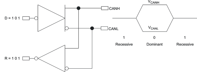
A fundamental CAN characteristic shown in Figure 4 is the opposite logic state between the bus, and the driver input and receiver output. Normally, a logic-high is associated with a one, and a logic-low is associated with a zero - but not so on a CAN bus. This is why TI CAN transceivers have the driver input and receiver output pins passively pulled high internally, so that in the absence of any input, the device automatically defaults to a recessive bus state on all input and output pins.
 Figure 4. The Inverted Logic of a CAN Bus
 Bus access is event-driven and takes place randomly. If two nodes try to occupy the bus simultaneously, access is implemented with a nondestructive, bit-wise arbitration. Nondestructive means that the node winning arbitration just continues on with the message, without the message being destroyed or corrupted by another node.
The allocation of priority to messages in the identifier is a feature of CAN that makes it particularly attractive for use within a real-time control environment. The lower the binary message identifier number, the higher its priority. An identifier consisting entirely of zeros is the highest priority message on a network because it holds the bus dominant the longest. Therefore, if two nodes begin to transmit simultaneously, the node that sends a last identifier bit as a zero (dominant) while the other nodes send a one (recessive) retains control of the CAN bus and goes on to complete its message. A dominant bit always overwrites a recessive bit on a CAN bus.
Note that a transmitting node constantly monitors each bit of its own transmission. This is the reason for the transceiver configuration of Figure 4 in which the CANH and CANL output pins of the driver are internally tied to the receiver's input. The propagation delay of a signal in the internal loop from the driver input to the receiver output is typically used as a qualitative measure of a CAN transceiver. This propagation delay is referred to as the loop time (tLOOP in a TI data sheet), but takes on varied nomenclature from vendor to vendor.
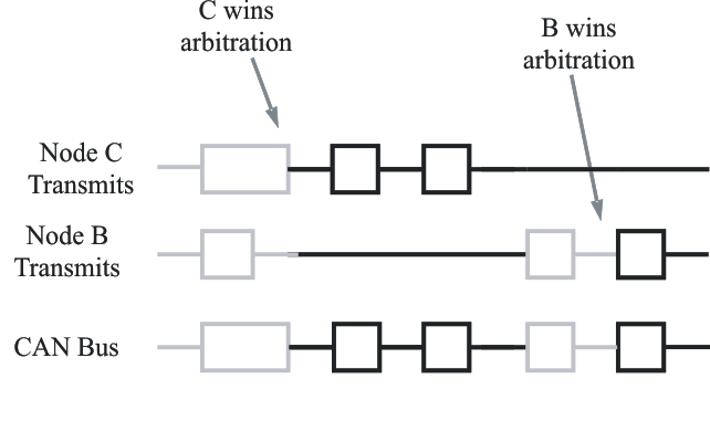
Figure 5 displays the CAN arbitration process that is handled automatically by a CAN controller. Because each node continuously monitors its own transmissions, as node B's recessive bit is overwritten by node C’s higher priority dominant bit, B detects that the bus state does not match the bit that it transmitted. Therefore, node B halts transmission while node C continues on with its message. Another attempt to transmit the message is made by node B once the bus is released by node C. This functionality is part of the ISO 11898 physical signaling layer, which means that it is contained entirely within the CAN controller and is completely transparent to a CAN user.
 Figure 5. Arbitration on a CAN Bus
 The allocation of message priority is up to a system designer, but industry groups mutually agree on the significance of certain messages. For example, a manufacturer of motor drives may specify that message 0010 is a winding current feedback signal from a motor on a CAN network and that 0011 is the tachometer speed. Because 0010 has the lowest binary identifier, messages relating to current values always have a higher priority on the bus than those concerned with tachometer readings.
In the case of DeviceNet™, devices from many manufacturers such as proximity switches and temperature sensors can be incorporated into the same system. Because the messages generated by DeviceNet sensors have been predefined by their professional association, the Open DeviceNet Vendors Association (ODVA), a certain message always relates to the specific type of sensor such as temperature, regardless of the actual manufacturer.