SLAU739 October   2017


  1.   MSP430FR2433 LaunchPad™ Development Kit (MSP‑EXP430FR2433)
    1.     Trademarks
    2. 1 Getting Started
      1. 1.1 Introduction
      2. 1.2 Key Features
      3. 1.3 What's Included
        1. 1.3.1 Kit Contents
        2. 1.3.2 Software Examples
      4. 1.4 First Steps: Out-of-Box Experience
        1. 1.4.1 Connecting to the Computer
        2. 1.4.2 Running the Out-of-Box Demo
      5. 1.5 Next Steps: Looking Into the Provided Code
    3. 2 Hardware
      1. 2.1 Block Diagram
      2. 2.2 Hardware Features
        1. 2.2.1 MSP430FR2433 MCU
        2. 2.2.2 eZ-FET Onboard Debug Probe With EnergyTrace Technology
        3. 2.2.3 Debug Probe Connection: Isolation Jumper Block
        4. 2.2.4 Application (or Backchannel) UART
        5. 2.2.5 Optional Features
          1. 2.2.5.1 Supercapacitor
      3. 2.3 Power
        1. 2.3.1 eZ-FET USB Power
        2. 2.3.2 BoosterPack and External Power Supply
        3. 2.3.3 Supercap (C6)
          1. 2.3.3.1 Charging the Supercap
          2. 2.3.3.2 Using the Supercap
          3. 2.3.3.3 Disabling the Supercap
      4. 2.4 Measure Current Draw of the MSP430 MCU
      5. 2.5 Clocking
      6. 2.6 Using the eZ-FET Debug Probe With a Different Target
      7. 2.7 BoosterPack Pinout
      8. 2.8 Design Files
        1. 2.8.1 Hardware
        2. 2.8.2 Software
      9. 2.9 Hardware Change log
    4. 3 Software Examples
      1. 3.1 Out-of-Box Software Example
        1. 3.1.1 Source File Structure
        2. 3.1.2 Overview
        3. 3.1.3 FRAM Data Logging Mode
        4. 3.1.4 Live Temperature Mode
      2. 3.2 Blink LED Example
        1. 3.2.1 Source File Structure
    5. 4 Resources
      1. 4.1 Integrated Development Environments
        1. 4.1.1 TI Cloud Development Tools
          1. 4.1.1.1 TI Resource Explorer Cloud
          2. 4.1.1.2 Code Composer Studio Cloud
        2. 4.1.2 Code Composer Studio IDE
        3. 4.1.3 IAR Embedded Workbench for Texas Instruments 430
      2. 4.2 LaunchPad Websites
      3. 4.3 MSPWare and TI Resource Explorer
      4. 4.4 FRAM Utilities
        1. 4.4.1 Compute Through Power Loss (CTPL)
        2. 4.4.2 Nonvolatile Storage (NVS)
      5. 4.5 MSP430FR2433 MCU
        1. 4.5.1 Device Documentation
        2. 4.5.2 MSP430FR2433 Code Examples
        3. 4.5.3 MSP430 Application Notes and TI Designs
      6. 4.6 Community Resources
        1. 4.6.1 TI E2E Community
        2. 4.6.2 Community at Large
    6. 5 FAQ
    7. 6 Schematics

Power

The board was designed to accommodate various powering methods, including through the onboard eZ-FET as well as from external or BoosterPack power. Figure 8 shows power from the ez-FET and power from external source through header J5 or the BoosterPack module.
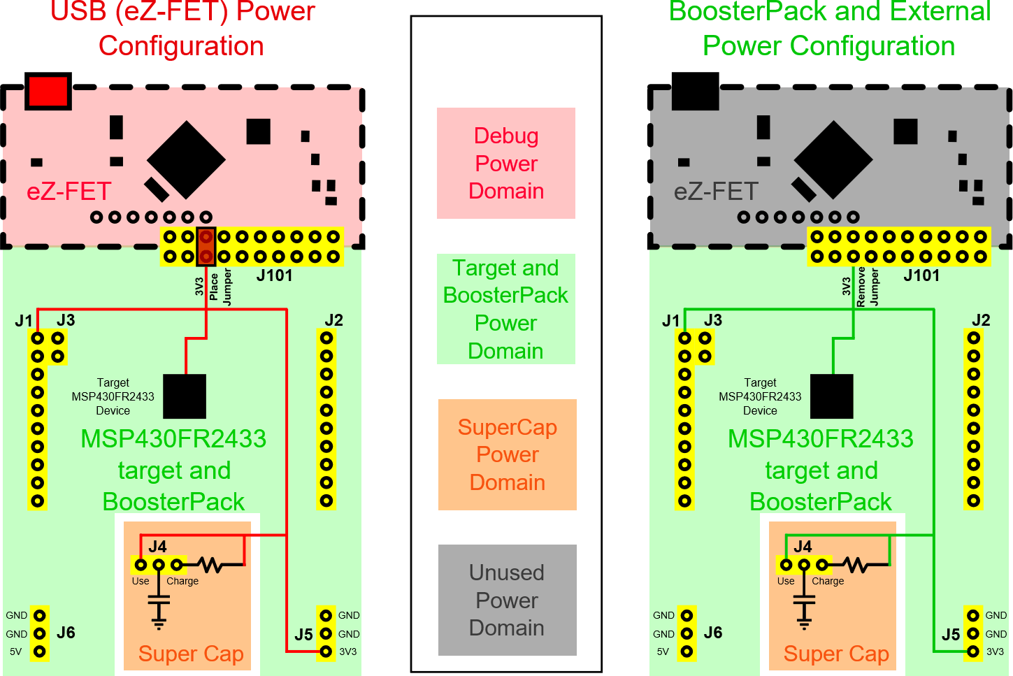
msp-exp430fr2433-power-block-diagram.pngFigure 8. MSP-EXP430FR2433 Power Block Diagram