SLAA899 December 2019 TAS2110 , TAS2555 , TAS2557 , TAS2559 , TAS2560 , TAS2562 , TAS2563 , TAS2564 , TAS2770
7 Design Consideration
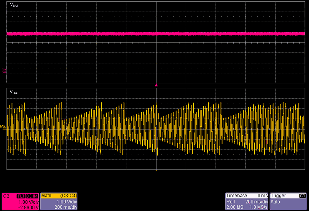
If the attack and release settings are set too aggressively for either the AGC or BOP, it is possible for a pumping behavior to be observed as shown in the figure below. In this example the BOP attack rate is very abrupt and the attenuation is set to the maximum. The VBAT supply was set with the output voltage just above the BOP threshold voltage and then the compliance current was decreased until the resulting ripple would trigger BOP. As a result we can observe a very dramatic drop in output voltage when the limiter attacks. Once the attack happens, VBAT recovers just enough allow the amplifier to release. This produces a repetitive attack and release cycle which produces an undesirable pumping behavior.
 Figure 11. Limiter Pumping Behavior
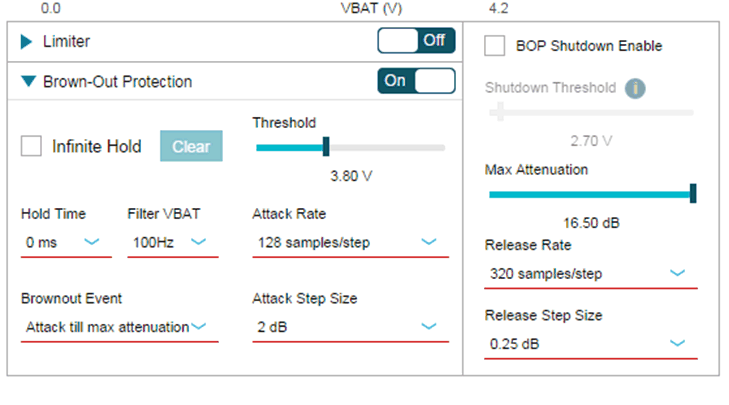
 If the settings force the attack and release to occur quickly enough, then it may produce audible artifacts. Notice the BOP settings in Figure 12 that were used to create the pumping behavior. Here the release is relatively slow, but attack is set to the maximum rate. Also, the attenuation is set to the maximum and VBAT filtering is not used.
 Figure 12. Limiter Pumping PPC3 Settings
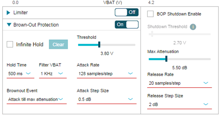
 To change this behavior, the hold time was set to 500 ms, VBAT filtering was set to a higher frequency, Attack step size was changed from 2 dB to 0.5 dB, and maximum attenuation was set to just 5.5 dB. Additionally, the release speed was increased significantly.
 Figure 13. Fixed PPC3 Settings
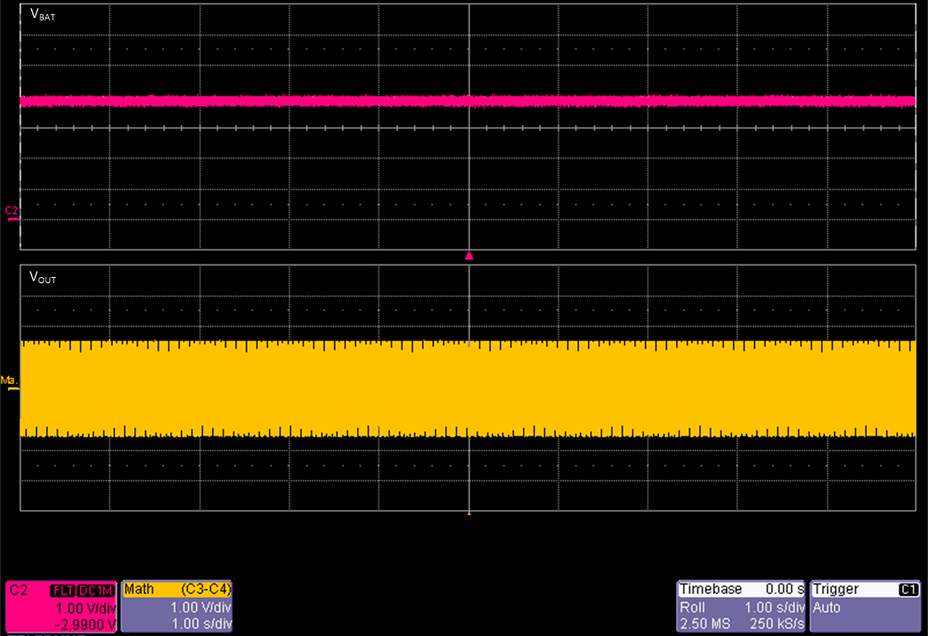
 With the settings in Figure 13 notice the new behavior with input and supply conditions unchanged.

Now the output remains at a constant level while the attack is active. We still gain the benefit of the attenuation, but the output level is now steady.