SLAA871 January   2019 AFE7422 , AFE7444


  1.   AFE74xx as a single-chip wideband repeater using loopback mode
    1.     Trademarks
    2. 1 Introduction
    3. 2 Repeater Mode (RX-TX Loopback With SerDes Bypassed)
      1. 2.1 Overview of the AFE74xx Repeater Mode
      2. 2.2 Configuration of the AFE74xx as a Repeater
      3. 2.3 Programming the Repeater Mode
        1. 2.3.1 Hardware Setup
        2. 2.3.2 Software Setup and GUI Configuration
    4. 3 130-MHz Digital Repeater System Overview
      1. 3.1 Key System Specifications
    5. 4 System Overview
      1. 4.1 Block Diagram
      2. 4.2 Design Considerations
      3. 4.3 Highlighted Products
        1. 4.3.1 LMK04828
      4. 4.4 System Design Theory
    6. 5 Hardware and Testing
      1. 5.1 Measured Latency and Gain
        1. 5.1.1 Hardware
        2. 5.1.2 Test Setup and Results
      2. 5.2 Measured Linearity Performance
        1. 5.2.1 Hardware and Test Setup
        2. 5.2.2 Test Results
      3. 5.3 Measured Selectivity (Out-of-Band Jammer)
        1. 5.3.1 Hardware and Test Setup
        2. 5.3.2 Test Results
    7. 6 Terminology

Test Results

Figure 16 and Figure 17 show that the before and after LTE ACPR measurements of the repeater are approximately 73 dB and 65 dB, respectively. The ACPR degradation caused by the receiver is approximately 9 dBm. Notice that the reference level offset in Figure 17 increased by 2 dB to account for the loss due to the filter and the extra SMA cables. The RX and TX DSAs were set to 1 and 0, respectively, in order to yield an overall gain of 6 dB.
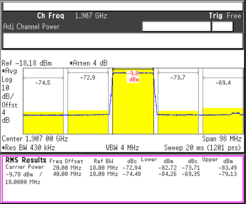
tida-060007-figure-x-clean-acpr-measurement-directly-from-dac38rf82-scope-shot.pngFigure 16. Clean ACPR Measurement Directly From DAC38RF82
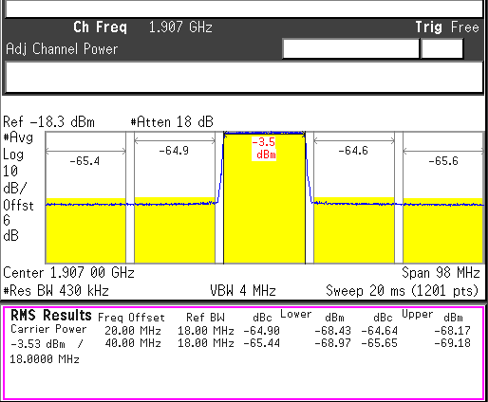
tida-060007-figure-x-repeater-acpr-measurement-from-output-shows-6-db-gain-of-waveform-8-db-acpr-degradation-scope-shot.pngFigure 17. Repeater ACPR Measurement From Output Shows 6-dB Gain of Waveform and 8-dB ACPR Degradation