SLAA450G April 2010 – April 2020
-
Creating a Custom Flash-Based Bootloader (BSL)
- Trademarks
- 1 5xx and 6xx Bootloader Customization
- 2
G2xx Bootloader Creation and Customization
- 2.1 Target System Specification
- 2.2 BSL Specification
- 2.3 Implementation
- 2.4
BSL Operation
- 2.4.1 Hardware Setup
- 2.4.2 Connection to Host
- 2.4.3 Operate BSL - Standard Sequence
- 2.4.4 Create New Code to Download Through BSL
- 2.4.5 Getting Ready for Production
- 3 Frequently Asked Questions (FAQ)
- Revision History
3 Frequently Asked Questions (FAQ)
- Question: Where can I download the source code and firmware images of the BSL 430?
- Question: What is the benefit having the Custom BSL programmed in protected memory and overwriting the TI factory BSL rather than just having the Custom BSL in main memory space?
- Question: Can the BSL be debugged?
- Question: How to switch from the BSL to an application?
- Question: What is the default BSL password for empty devices?
- Question: What does the MASS ERASE BSL command do?
- Question: If the device is protected using the JTAG Lock, is memory access still possible?
- Question: How to recover an overwritten BSL?
- Question: How to debug the BSL example code in IAR?
- Choose the project to execute. This example demonstrates how to choose the MSP430F543xA_TA_UART project.
- Check these settings: In the project options, under FET debugger, and the Download tab (see Figure 10), select the “Allow erase/write access to the BSL flash memory” and “Erase main and information memory”.
- After compiling the project, start the debug session.
- Open the Register View, and manually set the PC to 0x1000, which is the entry location of the BSL (see Figure 11).
- Run the BSL in the debugger. The program starts on the BSL entry function (see Figure 12).
- Question: How to debug the BSL example code in CCS?
- After the project is imported, go to the Project Properties, and configure the programming setup (see Figure 13).
- As Figure 13 shows, select Debug → MSP43x Options.
- Build the project (see Figure 14).
- Run the debug mode, pause the session, and then open the "Registers" view.
- Set the PC to 0x1000, which is the entry location of the BSL (see Figure 15).
- Continue the debug mode.
- When the debug mode is paused, the "Disassembly" view shows that the BSL is executed (see Figure 16).
- Add a breakpoint to debug the source code.
Answer: The source code and the firmware images are available from the CUSTOM-BSL430 link at Bootloader (BSL) for MSP low-power microcontrollers.
Answer: When the Custom BSL is programmed in the protected memory, it is secured from erasing and unintended execution. This configuration also supports the invoke sequence, where the bootcode executes the BSL when the invoke sequence is applied. In addition, the custom BSL does not occupy any of the main memory space.
Answer: Yes. After starting the debug session, set the Program Counter (PC) to point to the BSL entry location (@0x1000).
Answer: The factory BSL (also included in the Custom BSL) provides the SET PC command. This command sets the PC register to the given address to start the application.
Answer: The devices that come from the factory are erased, and the interrupt vectors are blank (0xFF). This means that the BSL password for initial programming is the default password (all 0xFF).
Answer: The MASS ERASE command erases all banks of the main memory. Information memory segments A to D and the BSL segments A to D are not erased.
Answer: Yes, by using BSL when the BSL is unlocked with the correct password.
Answer: If the BSL signature is corrupted or the BSL application is not functional, the BSL can still be recovered or reprogrammed using JTAG or SBW, as long as these interfaces are not locked.
Answer: The IAR project in the Custom BSL430 package was built in IAR 6.30.
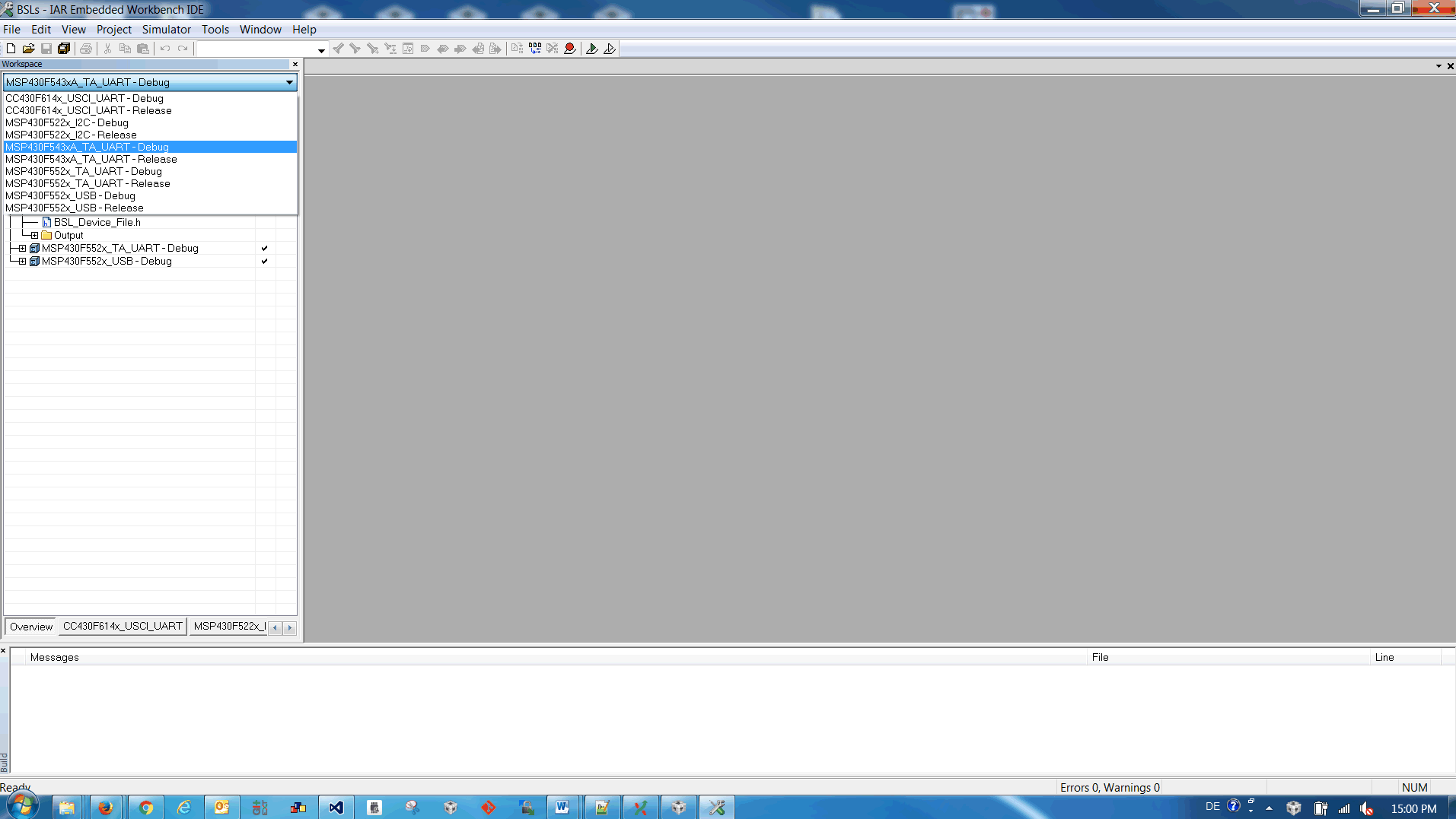 Figure 9. Select the Project
 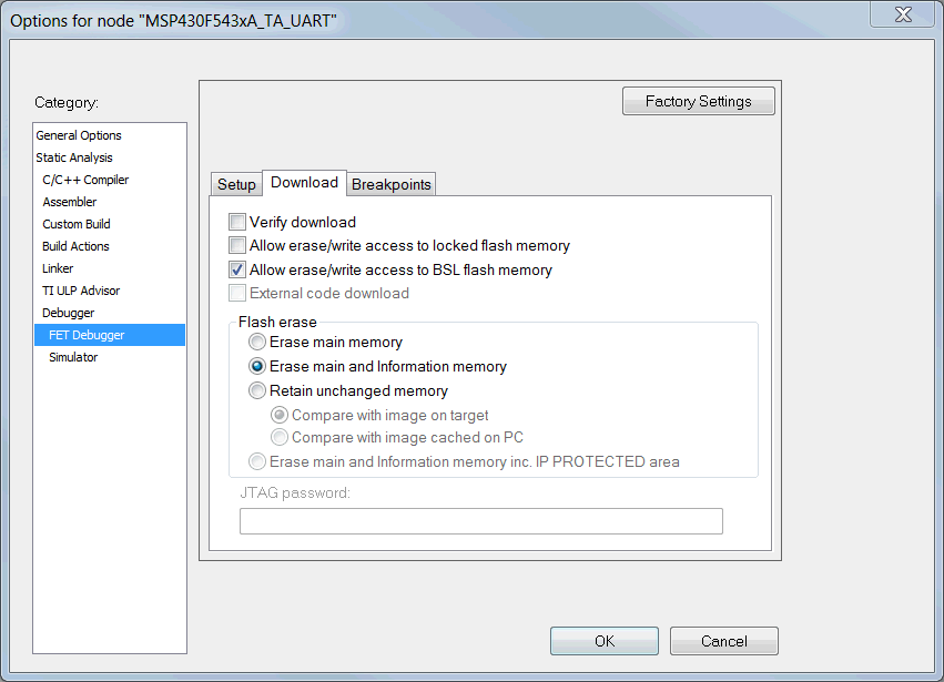 Figure 10. Setting in Project Properties
 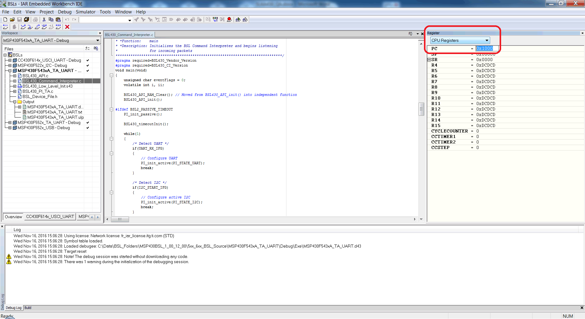 Figure 11. Set the PC to the Location of BSL
 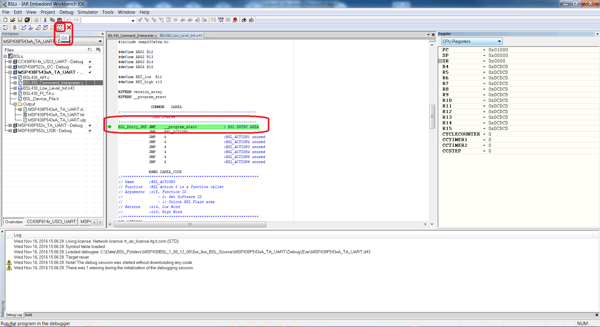 Figure 12. Run the Debug Session
 Answer: MSP430 Custom BSL 1.1.0 provides the CCS example that can be easily imported to CCS.
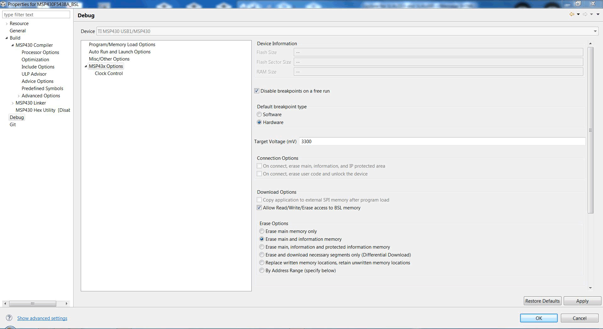 Figure 13. Debug Setup
 Under "Download Options", select "Allow Read/Write/Erase access to BSL memory".
Under "Erase Options", select "Erase main and information memory".
NOTE
Due to current compiler restraints in CCS, some Custom BSL combinations will not compile under 2KB memory. If the application must have the BSL completely in its 2KB memory region, use IAR to compile the custom BSL.
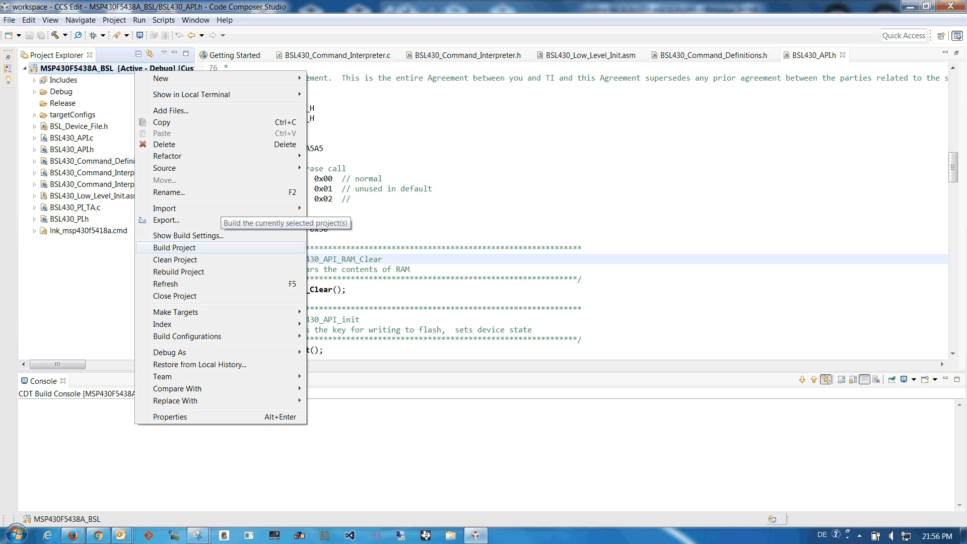 Figure 14. Build Project
 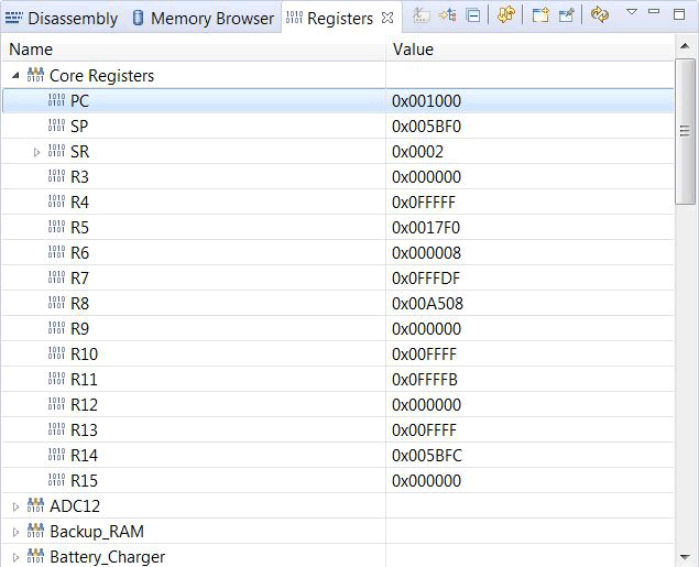 Figure 15. Set PC to BSL Address
 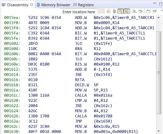 Figure 16. BSL is Executed