SLAA351A April 2007 – November 2018 MSP430F2232 , MSP430F2232 , MSP430F2234 , MSP430F2234 , MSP430F2252 , MSP430F2252 , MSP430F2254 , MSP430F2254 , MSP430F2272 , MSP430F2272 , MSP430F2274 , MSP430F2274
3.2 Timer_A
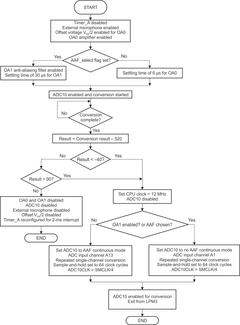
In this application, Timer_A is used to generate the periodic wake up every 2 ms. The timer clock is sourced from the on-chip VLO, which operates at 12 kHz at room temperature. The timer counter TACCR0 is set to a value to generate an interrupt every 2 ms at the VLO clock. The input signal measurement for a glass-breakage detect is done in the Timer_A interrupt service routine (ISR). The program flow is shown in Figure 6. The external microphone is first enabled, and then OA0 and/or OA1 is enabled, depending on the choice made to use the AAF. ADC10 is then enabled to convert the incoming signal either at channel A13 or channel A1. For completed conversions, the digitized samples are first converted to a bipolar format by subtracting a value equal to 520, which is approximately DVCC/2. The resulting value is compared to the thresholds –40 and +90, which distinguish spurious noisy inputs from a true sound event. In the absence of any sound event, all the peripherals are switched off with Timer_A reconfigured to work in LPM3 mode. On the other hand, if the sound levels are significant, the CPU clock is increased from 8 MHz to 12 MHz. ADC10 is reconfigured for repeated single-channel conversions at a sampling rate approximately of 39 ksps. Program control is passed on to the ADC10 ISR, which performs the signal analysis of the incoming signal to detect a glass breakage.
 Figure 6. Flowchart of Timer_A ISR Functionality