SCDU019 June 2021
7 8. PCB Layouts
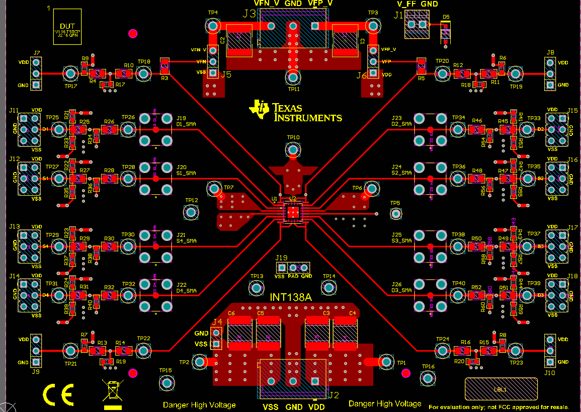
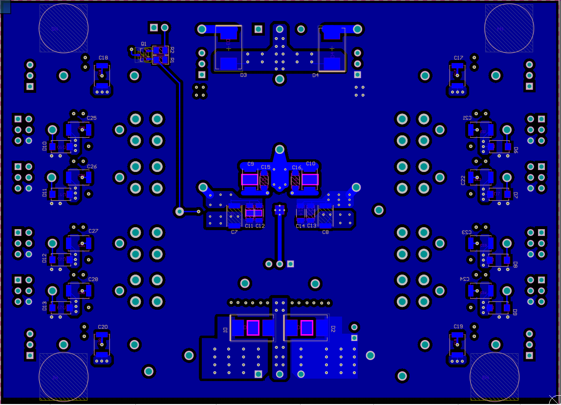
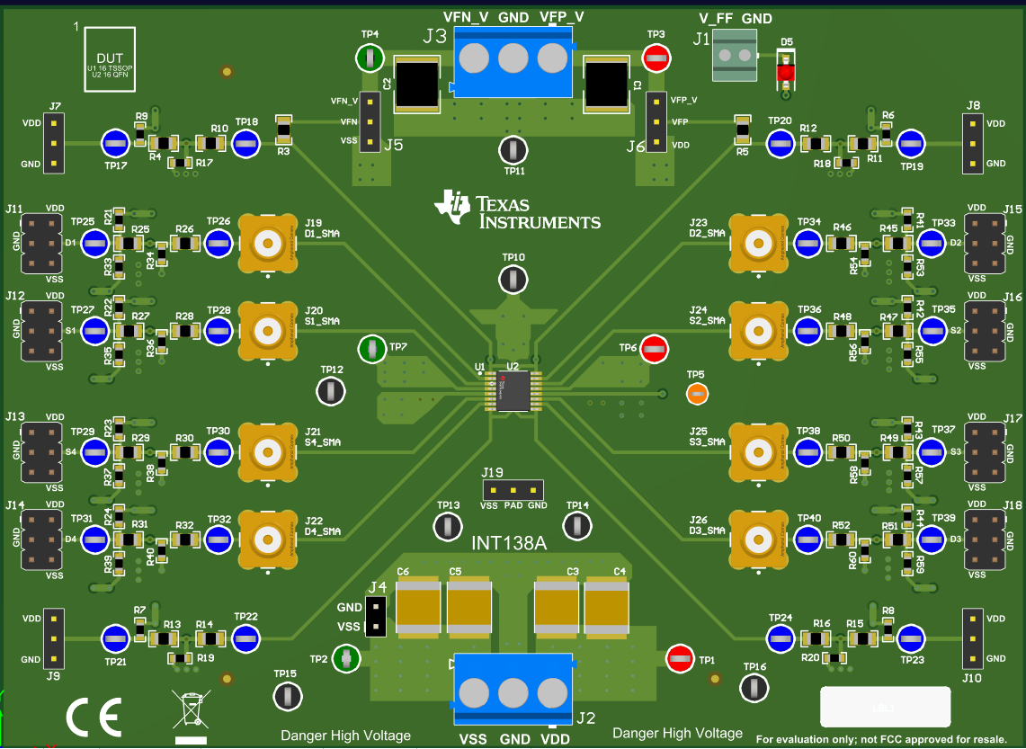
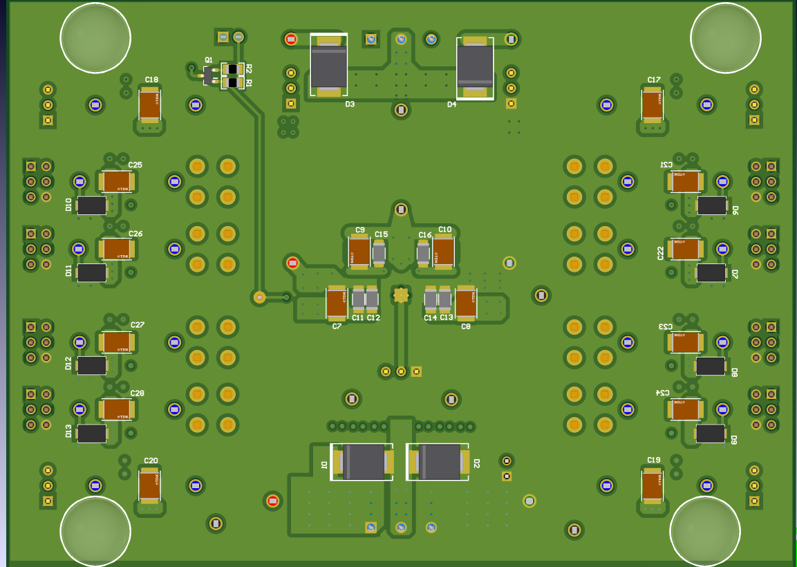
The PCB layouts are shown below. Figure 7-1 shows the 2D top view layout of the EVM, whereas Figure 7-2 shows the 2D bottom view. Figure 7-3 and Figure 7-4 show the 3D represenation of the layout for both top and bottom respectively.
 Figure 7-1 2D Top Side Layout View
 Figure 7-2 2D Bottom View Layout
 Figure 7-3 3D Top View of Layout
 Figure 7-4 3D Bottom View Of Layout