SBOU255 January 2021
3.2 Measurement Without Shunt
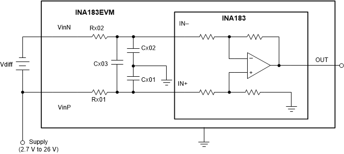
This connection method allows the user to either simulate the voltage developed across a sense resistor based on a given set of system conditions, or to connect the INA183EVM remotely to an existing shunt already included in an example application. Figure 3-2 illustrates a measurement configuration without a shunt.
To configure a measurement evaluation without a shunt, follow these procedures.
- Connect a differential voltage to VinP and VinN. Ensure that the VinP terminal is the more positive of the two inputs.
- Measure the output voltage at the OUT terminal.
 Figure 3-2 Measurement Without Shunt
Note:
The output voltage is equal to the gain of the device multiplied by the differential voltage measured directly at the device input pins.