SBOU240 October 2020
3.1 Improved Howland Current Pump
The OPA455EVM can be configured as an improved Howland current pump that provides an output current proportional to a single- or differential-input voltage. The improved Howland current pump is described and analyzed in section 3 of A Comprehensive Study of the Howland Current Pump Application Report. Information about how the current-pump resistor values are determined for a particular input voltage and a corresponding output current is provided in the application report. The report information is applied here in this section as a practical use for the OPA455EVM.
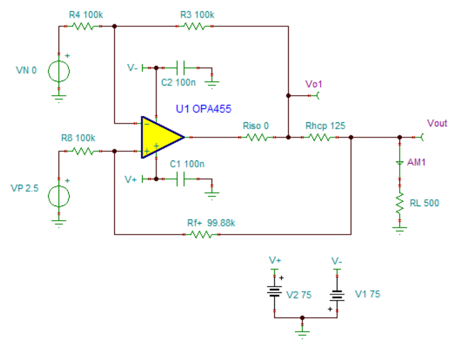
The OPA455EVM, as configured in Figure 3-1, sources on an output current of –20 mA when a single-ended input voltage of 2.5 V is applied to the VP input. If the input voltage sign is reversed, the output reverses direction and sinks 20 mA. The circuit in Figure 3-1 provides the resistance values required to obtain the correct 20-mA output current. The resistor and capacitor labels correspond to those screened on the OPA455EVM printed circuit board. As shown in Figure 3-1, when RL is equal to 500 Ω, the sourced output current level is –20 mA, and Vout is 10 V, as Ohm’s law dictates.
 Figure 3-1 Practical, 20-mA, Improved Howland Current-Pump Circuit
Practical current sources have a limited output voltage range that can be provided. The OPA455 op amp has a wide output voltage range because of the high-voltage supplies used. The OPA455 data sheet provides information about the linear output voltage range that should always be observed.
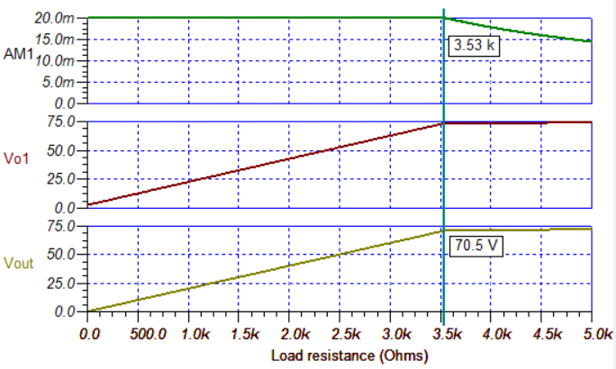
For the improved Howland current pump application, the output voltage (Vout) that is attainable at the load is further constrained by the voltage drop developed across R13. The 20-mA load current flows through the resistor, and develops a voltage drop. Therefore, with a fixed 20-mA output current flowing through RL, there is a limit as to how far Vout can swing. For this example, the limit occurs when Vout reaches approximately 70.5 V, and RL is 3.53 kΩ. This limit can be seen in Figure 3-2. Resistor RL can be any value from 0 Ω to 3.53 kΩ, and the output will remain within the circuit linear compliance range. However, if the value of RL is increased further, the current pump operation is forced outside the compliance range, and the output current will no longer remain constant. Thus, increasing the value of RL to greater than 3.53 kΩ defeats the goal of maintaining a constant current.
 Figure 3-2 Improved Howland Current Pump Output-Voltage Compliance Range
The improved Howland current pump can be used to generate an ac waveform with a peak current that corresponds to a maximum specified DC value. A 20-mA DC current source using the OPA455 has been demonstrated, and will now be used to show how a 20-mA peak AC-current waveform can be realized.
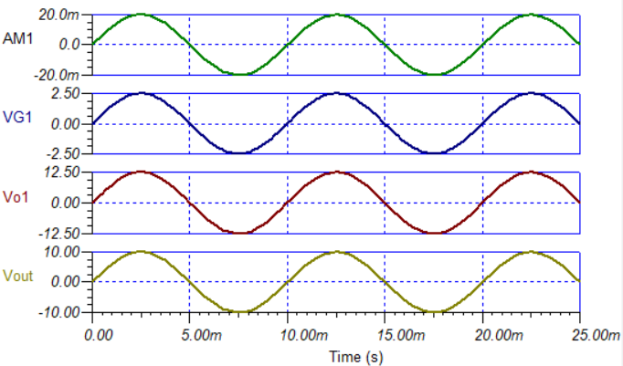
The same circuit shown in Figure 3-1 is applied, except the 2.5-VDC VP voltage source in Figure 3-1 is replaced by an 100-Hz AC sine wave source having a peak voltage of 2.5 V. The peak output current depends on the peak voltage level applied at the VP input. A sine wave is used in the example; however, a triangle wave, square wave, or other waveform could be applied instead. Figure 3-3 shows that a 2.5-V peak input sine wave applied to the current pump input, VP, results in a 20-mA peak sine wave at the output, Vout.
 Figure 3-3 Improved Howland Current Pump Applied as a Peak AC-Current Generator
The improved Howland current pump op amp circuit relies on both negative and positive feedback for operation; more negative feedback than positive feedback, but that feedback does not always provide stability. When unity-gain-stable op amps, such as the OPA455, are employed and they drive a resistive load, the op amp phase margin should be sufficient such that the circuit is stable. However, if the output load is complex, containing both resistive and reactive components (R±jX), there can be combinations that degrade the phase margin, and instability results. Degradation of the phase margin often occurs when the current pump is used to drive loads that are predominantly inductive.
The OPA455EVM has a number of positions where component may be added to stabilize the various OPA455 amplifier and improved Howland current pump configurations that are supported by the EVM. Some of the component locations that are used for this purpose are R6 (ISO), R5 (Rng), C12 (Cng, noise gain), R10 (Rsn), C16 (Csn, snubber), and C9 and C10 in the feedback loop. Compensation, when required, is determined based on the particular circuit to which the OPA455 is being applied. Op amp stability and compensation is a vast subject covered in numerous TI documents, and TI training programs such as TI Precision Labs – Op Amps.