ZHCSAK5C December   2012  – December 2015 ADS42B49

PRODUCTION DATA.  

  1. 特性
  2. 应用
  3. 说明
  4. 修订历史记录
  5. Description (continued)
  6. ADS424x and ADS422x Family Comparison
  7. Pin Configuration and Functions
  8. Specifications
    1. 8.1  Absolute Maximum Ratings
    2. 8.2  ESD Ratings
    3. 8.3  Recommended Operating Conditions
    4. 8.4  Thermal Information
    5. 8.5  Electrical Characteristics: ADS42B49 (250 MSPS)
    6. 8.6  Electrical Characteristics: General
    7. 8.7  Digital Characteristics
    8. 8.8  Timing Requirements: LVDS and CMOS Modes
    9. 8.9  Serial Interface Timing Characteristics
    10. 8.10 Reset Timing (Only When Serial Interface is Used)
    11. 8.11 LVDS Timings at Lower Sampling Frequencies
    12. 8.12 CMOS Timings at Lower Sampling Frequencies
    13. 8.13 Typical Characteristics
      1. 8.13.1 ADS42B49
      2. 8.13.2 Contour
  9. Parameter Measurement Information
  10. 10Detailed Description
    1. 10.1 Overview
    2. 10.2 Functional Block Diagram
    3. 10.3 Feature Description
      1. 10.3.1 Migrating from the ADS62P49 and ADS4249
      2. 10.3.2 Digital Functions
      3. 10.3.3 Gain for SFDR and SNR Trade-Off
      4. 10.3.4 Offset Correction
    4. 10.4 Device Functional Modes
      1. 10.4.1 Power-Down
        1. 10.4.1.1 Global Power-Down
        2. 10.4.1.2 Channel Standby
        3. 10.4.1.3 Input Clock Stop
      2. 10.4.2 Digital Output Information
        1. 10.4.2.1 Output Interface
        2. 10.4.2.2 DDR LVDS Outputs
        3. 10.4.2.3 LVDS Buffer
        4. 10.4.2.4 Parallel CMOS Interface
        5. 10.4.2.5 CMOS Interface Power Dissipation
        6. 10.4.2.6 Multiplexed Mode of Operation
        7. 10.4.2.7 Output Data Format
      3. 10.4.3 Parallel Configuration Details
    5. 10.5 Programming
      1. 10.5.1 Parallel Configuration Only
      2. 10.5.2 Serial Interface Configuration Only
      3. 10.5.3 Using Both Serial Interface and Parallel Controls
      4. 10.5.4 Serial Interface Details
        1. 10.5.4.1 Register Initialization
        2. 10.5.4.2 Serial Register Readout
    6. 10.6 Register Maps
      1. 10.6.1 Register Description
  11. 11Application and Implementation
    1. 11.1 Application Information
      1. 11.1.1 Driving Circuit
        1. 11.1.1.1 Drive Circuit Requirements
      2. 11.1.2 Clock Input
    2. 11.2 Typical Application
      1. 11.2.1 Design Requirements
      2. 11.2.2 Detailed Design Procedure
        1. 11.2.2.1 Analog Input
        2. 11.2.2.2 Clock Driver
        3. 11.2.2.3 Digital Interface
      3. 11.2.3 Application Curves
  12. 12Power Supply Recommendations
    1. 12.1 Using DC/DC Power Supplies
    2. 12.2 Power Supply Bypassing
  13. 13Layout
    1. 13.1 Layout Guidelines
      1. 13.1.1 Grounding
      2. 13.1.2 Supply Decoupling
      3. 13.1.3 Exposed Pad
      4. 13.1.4 Routing Analog Inputs
    2. 13.2 Layout Example
  14. 14器件和文档支持
    1. 14.1 器件支持
      1. 14.1.1 器件命名规则
    2. 14.2 文档支持
      1. 14.2.1 相关文档 
    3. 14.3 社区资源
    4. 14.4 商标
    5. 14.5 静电放电警告
    6. 14.6 Glossary
  15. 15机械、封装和可订购信息

封装选项

机械数据 (封装 | 引脚)
散热焊盘机械数据 (封装 | 引脚)
订购信息

1 特性

  • 最大采样速率:250 MSPS
  • 超低功耗:
    • 250 MSPS 时总体功耗 850mW
  • 集成型模拟输入缓冲器:
    • 输入电容:170MHz 时为 2.2pF
    • 输入电阻:170MHz 时为 1.1kΩ
  • 高动态性能:
    • 170MHz 时无杂散动态范围 (SFDR) 为 85dBc
    • 170MHz 时信噪比 (SNR) 为 70.7dBFS
  • 串扰:185MHz 时小于 85dB
  • 针对
    SNR 和 SFDR 折衷的可编程增益高达 6dB
  • DC 偏移校正
  • 输出接口选项:
    • 1.8V 并行 CMOS 接口
    • 支持可编程摆幅的双倍数据速率 (DDR) 低压动态信令 (LVDS):
      • 标准摆幅:350mV
      • 低摆幅:200mV
  • 支持低输入时钟振幅
    低至 200mVPP
  • 封装:9.00mm x 9.00mm,64 引脚四方扁平无引线 (VQFN) 封装

2 应用

  • 无线通信基础设施
  • 软件定义无线电
  • 功率放大器线性化

3 说明

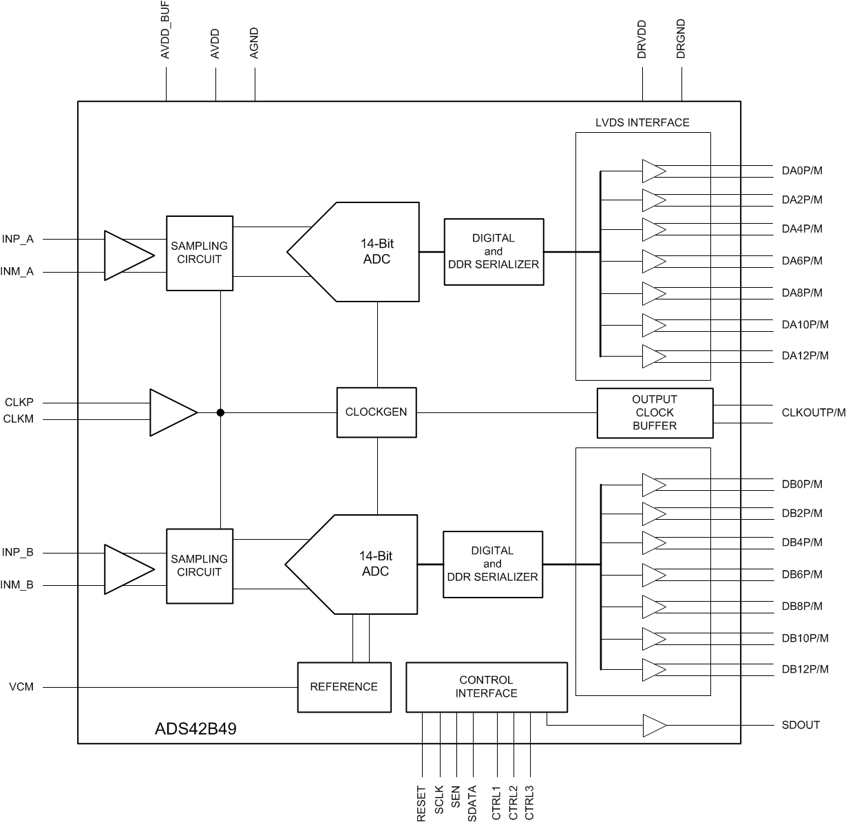
ADS42B49 是一款特有集成型模拟输入缓冲器的超低功耗双通道,14 位模数转换器 (ADC)。它使用创新性设计技巧以实现高动态性能,同时能耗极低。器件中的模拟输入缓冲器使得它易于驱动并且有助于在宽频率范围内实现高性能。ADS42B49 非常适合于多载波、高带宽通信 应用。

器件信息(1)

器件型号 封装 封装尺寸(标称值)
ADS42B49 VQFN(64) 9.00mm x 9.00mm
  1. 要了解所有可用封装,请见数据表末尾的可订购产品附录。

框图

ADS42B49 FBD_SBAS558.gif