SLUS828D December 2008 – October 2017 UCC28019A
PRODUCTION DATA.
- 1 Features
- 2 Applications
- 3 Description
- 4 Revision History
- 5 Pin Configuration and Functions
- 6 Specifications
-
7 Detailed Description
- 7.1 Overview
- 7.2 Functional Block Diagram
- 7.3
Feature Description
- 7.3.1 Soft-Start
- 7.3.2
System Protection
- 7.3.2.1 VCC Undervoltage Lockout (UVLO)
- 7.3.2.2 Input Brown-Out Protection (IBOP)
- 7.3.2.3 Output Overvoltage Protection (OVP)
- 7.3.2.4 Open Loop Protection/Standby (OLP/Standby)
- 7.3.2.5 ISENSE Open-Pin Protection (ISOP)
- 7.3.2.6 Output Undervoltage Detection (UVD) and Enhanced Dynamic Response (EDR)
- 7.3.2.7 Over-Current Protection
- 7.3.2.8 Soft Over Current (SOC)
- 7.3.2.9 Peak Current Limit (PCL)
- 7.3.2.10 Current Sense Resistor, RISENSE
- 7.3.3 Gate Driver
- 7.3.4 Current Loop
- 7.3.5 ISENSE and ICOMP Functions
- 7.3.6 Pulse Width Modulator
- 7.3.7 Control Logic
- 7.3.8 Voltage Loop
- 7.3.9 Output Sensing
- 7.3.10 Voltage Error Amplifier
- 7.3.11 Non-Linear Gain Generation
- 7.4 Device Functional Modes
- 8 Application and Implementation
- 9 Power Supply Recommendations
- 10Layout
- 11Device and Documentation Support
- 12Mechanical, Packaging, and Orderable Information
1 Features
- 8-Pin Solution Reduces External Components
- Wide-Range Universal AC Input Voltage
- Fixed 65-kHz Operating Frequency
- Maximum Duty Cycle of 98% (typ.)
- Output Over/Undervoltage Protection
- Input Brown-Out Protection
- Cycle-by-Cycle Peak Current Limiting
- Open Loop Detection
- Low-Power User-Controlled Standby Mode
2 Applications
- CCM Boost Power Factor Correction Power Converters in the 100 W to >2 kW Range
- Digital TV
- Home Electronics
- White Goods and Industrial Electronics
- Server and Desktop Power Supplies
3 Description
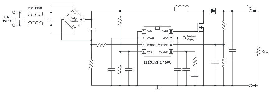
The UCC28019A 8-pin active Power Factor Correction (PFC) controller uses the boost topology operating in Continuous Conduction Mode (CCM). The controller is suitable for systems in the 100 W to >2 kW range over a wide-range universal ac line input. Start-up current during undervoltage lockout is less than 200 μA. The user can control low power standby mode by pulling the VSENSE pin below 0.77 V.
Low-distortion wave shaping of the input current using average current mode control is achieved without input line sensing, reducing the external component count. Simple external networks allow for flexible compensation of the current and voltage control loops. The switching frequency is internally fixed and trimmed to better than ±5% accuracy at 25°C. Fast 1.5-A peak gate current drives the external switch.
Numerous system-level protection features include peak current limit, soft over-current, open-loop detection, input brown-out, and output over/undervoltage. Soft-start limits boost current during start-up. A trimmed internal reference provides accurate protection thresholds and a regulation set-point. An internal clamp limits the gate drive voltage to 12.5 V.
Device Information(1)
| PART NUMBER | PACKAGE | BODY SIZE (NOM) |
|---|---|---|
| UCC28019A | SOIC (8) | 3.91 mm × 4.9 mm |
| PDIP (8) | 6.35 mm × 9.81 mm |
- For all available packages, see the orderable addendum at the end of the data sheet.
Simplified Schematic
