ZHCSN51K June 2007 – June 2024 TPS74901
PRODUCTION DATA
- 1
- 1 特性
- 2 应用
- 3 说明
- 4 Pin Configuration and Functions
- 5 Specifications
- 6 Detailed Description
- 7 Application and Implementation
- 8 Device and Documentation Support
- 9 Revision History
- 10Mechanical, Packaging, and Orderable Information
封装选项
机械数据 (封装 | 引脚)
散热焊盘机械数据 (封装 | 引脚)
订购信息
7.4.1.2 Thermal Considerations
A better method of estimating the thermal measure comes from using the thermal metrics ΨJT and ΨJB, as shown in Equation 6. These metrics are a more accurate representation of the heat transfer characteristics of the die and the package than RθJA. The junction temperature can be estimated with the corresponding formulas given in Equation 6.
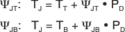
where:
- PD is the power dissipation shown by Equation 4
- TT is the temperature at the center-top of the device package
- TB is the PCB temperature measured 1mm away from the device package on the PCB surface (see Figure 7-8)
Both TT and TB can be measured on actual application boards using a thermo-gun (an infrared thermometer).
For more information about measuring TT and TB, see the Using New Thermal Metrics application note, available for download at www.ti.com.

Compared with RθJA, the thermal metrics ΨJT and ΨJB are less independent of board size but do have a small dependency on board size and layout. Figure 7-9 shows characteristic performance of ΨJT and ΨJB versus board size.
Referring to Figure 7-9, the RGW package thermal performance has negligible dependency on board size. The KTW package, however, does have a measurable dependency on board size. This dependency exists because the package shape is not point symmetric to the center of a device. In the KTW package, for example (see Figure 7-8), silicon is not beneath the measuring point of TT that is the center of the X and Y dimension, so that ΨJT has a dependency. Also, because of that non-point symmetry, device heat distribution on the PCB is not point symmetric either, so that ΨJB has a greater dependency on board size and layout.
 Figure 7-9 ΨJT and ΨJB versus Board Size
For a more detailed discussion of why TI does not recommend using RθJC(top) to determine thermal characteristics, see the Using New Thermal Metrics application note, available for download at www.ti.com. Also, see the IC Package Thermal Metrics application note (also available on the TI website) for further information.