ZHCSE51 September 2015 TPS657095
PRODUCTION DATA.
- 1 特性
- 2 应用
- 3 说明
- 4 修订历史记录
- 5 Pin Configuration and Functions
- 6 Specifications
-
7 Detailed Description
- 7.1 Overview
- 7.2 Functional Block Diagram
- 7.3
Feature Description
- 7.3.1 State Diagram
- 7.3.2 Power-up Timing
- 7.3.3 GPO
- 7.3.4 GPIO
- 7.3.5 LED_EN
- 7.3.6 Minimum-On-Time Feature
- 7.3.7 PWM Dimming
- 7.3.8 Crystal Oscillator and CLKOUT
- 7.3.9 LDOs
- 7.3.10 Undervoltage Lockout
- 7.3.11 Power Up/Power Down Default States
- 7.3.12 Output Voltage Discharge for LDO1 and LDO2
- 7.3.13 Power-Good Status Bits for LDO1 and LDO2
- 7.3.14 Short-Circuit Protection
- 7.3.15 Thermal Shutdown
- 7.3.16 LED Driver
- 7.3.17 4kByte OTP Memory
- 7.4 Device Functional Modes
- 7.5 Programming
- 7.6
Register Map
- 7.6.1 DEV_AND_REV_ID Register Address: 00h
- 7.6.2 OTP_REV Register Address: 01h
- 7.6.3 GPIO_CTRL Register Address: 02h
- 7.6.4 PWM_OSC_CNTRL Register Address: 03h
- 7.6.5 ISINK_CURRENT Register Address: 04h
- 7.6.6 LDO_CTRL Register Address: 05h
- 7.6.7 LDO1_VCTRL Register Address: 06h
- 7.6.8 LDO2_VCTRL Register Address: 07h
- 7.6.9 PWM_DUTY_THR_L Register Address: 08h
- 7.6.10 PWM_DUTY_THR_H Register Address: 09h
- 7.6.11 MIN_ON_TIME_THR Register Address: 0Ah
- 7.6.12 PWM_DUTY_L Register Address: 0Bh
- 7.6.13 PWM_DUTY_H Register Address: 0Ch
- 7.6.14 MIN_ON_TIME Register Address: 0Dh
- 7.6.15 SPARE Register Address: 0Eh
- 7.6.16 4K_OTP_PASSWORD Register Address: 0Fh
- 8 Application and Implementation
- 9 Power Supply Recommendations
- 10Layout
- 11器件和文档支持
- 12机械、封装和可订购信息
12 机械、封装和可订购信息
以下页中包括机械、封装和可订购信息。 这些信息是针对指定器件可提供的最新数据。 这些数据会在无通知且不对本文档进行修订的情况下发生改变。 欲获得该数据表的浏览器版本,请查阅左侧的导航栏。
12.1 封装概要
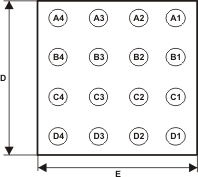
 Figure 42. 芯片尺寸封装
(底视图)
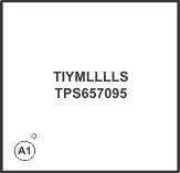
 Figure 43. 芯片尺寸封装
(顶视图)
代码:
- YM — 年月日代码
- LLLL — 批次追踪代码
- S — 组装地点代码
12.2 芯片尺寸封装尺寸
TPS657095 器件采用 16 焊锡凸块芯片尺寸封装(YFF, NanoFree™)。 封装尺寸如下:
- D = ca. 1700 ± 25μm
- E = 大约 1700 ± 25μm