ZHCSGE4B December 2010 – March 2017 TPS61240-Q1
PRODUCTION DATA.
1 特性
2 应用
- 高级驾驶员辅助系统 (ADAS)
- 前置摄像头
- 环视系统 ECU
- 雷达和 LIDAR
- 汽车信息娱乐系统和仪表板
- 音响主机
- HMI 和显示
- 车身电子装置和照明
- 工厂自动化与控制
3 说明
TPS61240-Q1 器件是一款高效同步升压直流/直流转换器,经过优化,可用于由三节碱性/镍镉/镍氢电池或单节锂离子/锂聚合物电池供电的产品。TPS61240-Q1 支持高达 450mA 的输出电流。TPS61240-Q1 的输入谷值电流限值为 500mA。
TPS61240-Q1 器件可在 2.3V 至 5.5V 的输入电压范围内提供 5V(典型值)固定输出电压,而且支持具有更大电压范围的电池。停机期间,负载与电池完全断开。TPS61240-Q1 升压转换器基于准恒定导通时间谷值电流模式控制方案。
关断时,TPS61240-Q1 在输出电压引脚处呈现高阻抗。因此,该器件适用于在 TPS61240-Q1 关断时 需要由其他电源驱动 稳压输出总线的应用。
在轻负载期间,该器件将自动脉冲跳跃,以最低静态电流实现最高效率。在关断模式下,电流消耗减少至 1μA 以下。
TPS61240-Q1 允许使用小型电感器和电容器,因此可实现较小的解决方案尺寸。TPS61240-Q1 采用 2mm × 2mm WSON 封装。
器件信息(1)
| 器件型号 | 封装 | 封装尺寸(标称值) |
|---|---|---|
| TPS61240-Q1 | WSON (6) | 2.00mm × 2.00mm |
- 如需了解所有可用封装,请参阅数据表末尾的可订购产品附录。
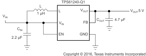
简化原理图

4 修订历史记录
Changes from A Revision (October 2016) to B Revision
- Added 关于特性部分的 AEC-Q100 认证信息Go
- Added operating ambient temperature for T version of device (TPS61240TDRVRQ1) in the Recommended Operating Conditions tableGo
- Added shutdown current for T version of device (TPS61240TDRVRQ1) in the Electrical Characteristics tableGo
- Changed 静电放电注意事项声明Go
Changes from * Revision (December 2010) to A Revision
- 添加了应用部分、ESD 额定值表、特性 说明部分、器件功能模式、应用和实施部分、电源相关建议部分,布局部分、器件和文档支持部分以及机械、封装和可订购信息部分Go
- Changed 通篇将 TPS6124x 更改为 TPS61240-Q1 Go
- Changed 说明部分Go
- Deleted 订购信息表Go
- Changed Pin Functions figure and table Go
- Deleted Dissipation Ratings tableGo
- Added Inductance and Output capacitance values and table note to Recommended Operating Conditions Go
- Added Thermal Information tableGo
- Changed reference to Typical Applications section Go
- Changed VOUT test condition to 2.3 V to ≤ VIN ≤ VOUT Go
- Added equals before 2.3 V in Output current test condition Go
- Removed ISW from all rows except Switch valley current limit Go
- Changed Operating quiescent current test condition by adding device not switching Go
- Added equals before 600 mVp-p in Line transient response test condition Go
- Moved figures 8 through 16 to Application Curves section Go
- Updated titles of figures 2 through 7 for better clarity Figure 2 Go
- Deleted Parameter Measurement Information section Go
- Changed Updated Overview section for more clarity Go
- Changed Figure 8 Inductor/Rectifier Currents in Current Limit Operation waveformGo
- Added Under no load conditions to Soft Start sectionGo
- Deleted HDMI / USB-OTG Application title Go
- Updated Inductor Selection sectionGo
- Deleted List of Inductors table and listed one example inductor in descriptionGo
- Changed 2.7 µF to 2.3 µF in Output Capacitor section Go