ZHCS360F July   2012  – November 2020 TPS54020

PRODUCTION DATA  

  1. 特性
  2. 应用
  3. 说明
  4. Revision History
  5. Description (Continued)
  6. Pin Configuration and Functions
  7. Specifications
    1. 7.1 Absolute Maximum Ratings (1)
    2. 7.2 ESD Ratings
    3. 7.3 Recommended Operating Conditions
    4. 7.4 Thermal Information
    5. 7.5 Electrical Characteristics
    6. 7.6 Typical Characteristics
  8. Detailed Description
    1. 8.1 Overview
    2. 8.2 Functional Block Diagram
    3. 8.3 Feature Description
      1. 8.3.1  Fixed Frequency PWM Control
      2. 8.3.2  Input Voltage and Power Input Voltage Pins (VIN and PVIN)
      3. 8.3.3  Voltage Reference (VREF)
      4. 8.3.4  Adjusting the Output Voltage
      5. 8.3.5  Safe Start-up into Prebiased Outputs
      6. 8.3.6  Error Amplifier
      7. 8.3.7  Slope Compensation
      8. 8.3.8  Enable and Adjusting Undervoltage Lockout
      9. 8.3.9  Adjustable Switching Frequency and Synchronization (RT/CLK)
      10. 8.3.10 Soft-Start (SS) Sequence
      11. 8.3.11 Power Good (PWRGD)
      12. 8.3.12 Bootstrap Voltage (BOOT) and Low Dropout Operation
      13. 8.3.13 Sequencing (SS)
      14. 8.3.14 Output Overvoltage Protection (OVP)
      15. 8.3.15 Overcurrent Protection
        1. 8.3.15.1 High-side MOSFET Overcurrent Protection
        2. 8.3.15.2 Low-side MOSFET Overcurrent Protection
      16. 8.3.16 Thermal Shutdown
    4. 8.4 Device Functional Modes
      1. 8.4.1 Single-Supply Operation
      2. 8.4.2 Split Rail Operation
      3. 8.4.3 Continuous Current Mode Operation (CCM)
      4. 8.4.4 Eco-mode Light-Load Efficiency Operation
      5. 8.4.5 Adjustable Switching Frequency (RT Mode)
      6. 8.4.6 Synchronization (CLK Mode)
  9. Application and Implementation
    1. 9.1 Application Information
      1. 9.1.1 Small Signal Model for Loop Response
      2. 9.1.2 Simple Small Signal Model for Peak Current Mode Control
      3. 9.1.3 Small Signal Model for Frequency Compensation
      4. 9.1.4 Designing the Device Loop Compensation
        1. 9.1.4.1 Step One: Determine the Crossover Frequency (fC)
        2. 9.1.4.2 Step Two: Determine a Value for R6
        3. 9.1.4.3 Step Three: Calculate the Compensation Zero.
        4. 9.1.4.4 Step Four: Calculate the Compensation Noise Pole.
        5. 9.1.4.5 Step Five: Calculate the Compensation Phase Boost Zero.
      5. 9.1.5 Fast Transient Considerations
    2. 9.2 Typical Application
      1. 9.2.1 Design Requirements
      2. 9.2.2 Detailed Design Procedure
        1. 9.2.2.1  Custom Design With WEBENCH® Tools
        2. 9.2.2.2  Operating Frequency
        3. 9.2.2.3  Output Inductor Selection
        4. 9.2.2.4  Output Capacitor Selection
          1. 9.2.2.4.1 Response to a Load Transient
          2. 9.2.2.4.2 Output Voltage Ripple
          3. 9.2.2.4.3 Bus Capacitance
        5. 9.2.2.5  Input Capacitor Selection
        6. 9.2.2.6  Soft-Start Capacitor Selection
        7. 9.2.2.7  Bootstrap Capacitor Selection
        8. 9.2.2.8  Undervoltage Lockout Set Point
        9. 9.2.2.9  Output Voltage Feedback Resistor Selection
          1. 9.2.2.9.1 Minimum Output Voltage
        10. 9.2.2.10 Compensation Component Selection
      3. 9.2.3 Application Curves
  10. 10Power Supply Recommendations
  11. 11Layout
    1. 11.1 Layout Guidelines
    2. 11.2 Layout Examples
  12. 12Device and Documentation Support
    1. 12.1 Device Support
      1. 12.1.1 Development Support
        1. 12.1.1.1 Custom Design With WEBENCH® Tools
    2. 12.2 Documentation Support
      1. 12.2.1 Related Documentation
    3. 12.3 Receiving Notification of Documentation Updates
    4. 12.4 Support Resources
    5. 12.5 Trademarks
    6. 12.6 Electrostatic Discharge Caution
    7. 12.7 Glossary
  13. 13Mechanical, Packaging, and Orderable Information

封装选项

机械数据 (封装 | 引脚)
散热焊盘机械数据 (封装 | 引脚)
订购信息

说明

TPS54020 是一款 10A、4.5V 到 17V 输入 SWIFT 转换器。该器件采用创新型 3.5mm × 3.5mm HotRod 封装,能够优化高密度降压设计。TPS54020 是一款功能全面的转换器。

通过高侧和低侧 MOSFET 的创新集成和封装实现了高效率。TPS54020 可在较高的负载条件下保持持续电流模式 (CCM) 运行,并能够在跳过脉冲时切换到 Eco 模式以提升轻载效率。

两个 MOSFET 上的电流限制提供器件和系统的保护。高侧 MOSFET 内的逐周期电流限制在过载情况下提供保护。低侧 MOSFET 零电流检测在轻负载运行时关闭低侧 MOSFET。共有三种限流阈值可供选择,能够适用于多种应用。也可选择一个断续或逐周期过流保护机制。

当芯片温度超过热关断触发点时,热关断保护禁用开关,而在内置热滞后和关断断续时间后启用开关。

器件信息
器件型号 封装(1) 封装尺寸(标称值)
TPS54020 VQFN (15) 3.50mm x 3.50mm
如需了解所有可用封装,请见数据表末尾的可订购产品附录。
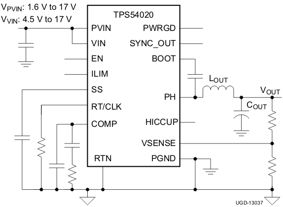
GUID-1FD7B72C-19D1-451A-9905-745D74F582FE-low.gif简化版应用电路原理图
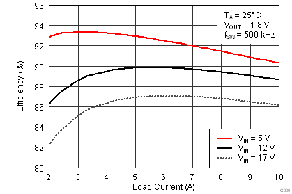
GUID-E9819195-9CF4-44EE-A13F-391697DA11E3-low.png效率与负载电流间的关系