ZHCS767B January   2012  – April 2016 TPA2080D1

PRODUCTION DATA.  

  1. 特性
  2. 应用
  3. 说明
    1.     Device Images
  4. 修订历史记录
  5. 器件比较表
  6. Pin Configuration and Functions
    1.     Pin Functions
  7. Specifications
    1. 7.1 Absolute Maximum Ratings
    2. 7.2 ESD Ratings
    3. 7.3 Recommended Operating Conditions
    4. 7.4 Thermal Information
    5. 7.5 Electrical Characteristics
    6. 7.6 Operating Characteristics
    7. 7.7 Typical Characteristics
  8. Parameter Measurement Information
  9. Detailed Description
    1. 9.1 Overview
    2. 9.2 Functional Block Diagram
    3. 9.3 Feature Description
      1. 9.3.1 Fully Differential Amplifier
        1. 9.3.1.1 Advantages of Fully Differential Amplifiers
      2. 9.3.2 Short-Circuit Auto-Recovery
      3. 9.3.3 Operation With DACs and CODECs
      4. 9.3.4 Speaker Load Limitation
      5. 9.3.5 Filter-Free Operation and Ferrite Bead Filters.
      6. 9.3.6 Boost Converter Auto Pass Through (APT)
    4. 9.4 Device Functional Modes
      1. 9.4.1 Shutdown Mode
  10. 10Application and Implementation
    1. 10.1 Application Information
    2. 10.2 Typical Application
      1. 10.2.1 TPA2080D1 With Differential Input Signal
        1. 10.2.1.1 Design Requirements
        2. 10.2.1.2 Detailed Design Procedure
          1. 10.2.1.2.1 Surface Mount Inductor
          2. 10.2.1.2.2 Inductor Selection
          3. 10.2.1.2.3 Surface Mount Capacitors
          4. 10.2.1.2.4 Boost Converter Capacitor Selection
          5. 10.2.1.2.5 Decoupling Capacitors
          6. 10.2.1.2.6 Input Capacitors
          7. 10.2.1.2.7 Boost Converter Component Section
        3. 10.2.1.3 Application Curves
      2. 10.2.2 TPA2080D1 With Single-Ended Signals.
        1. 10.2.2.1 Design Requirements
        2. 10.2.2.2 Detailed Design Procedure
        3. 10.2.2.3 Application Curves
  11. 11Power Supply Recommendations
    1. 11.1 Power Supply Decoupling Capacitors
  12. 12Layout
    1. 12.1 Layout Guidelines
      1. 12.1.1 Component Placement
      2. 12.1.2 Thermal Considerations
      3. 12.1.3 Pad Size
    2. 12.2 Layout Example
  13. 13器件和文档支持
    1. 13.1 器件支持
      1. 13.1.1 第三方产品免责声明
      2. 13.1.2 器件命名规则
        1. 13.1.2.1 升压项
    2. 13.2 社区资源
    3. 13.3 商标
    4. 13.4 静电放电警告
    5. 13.5 Glossary
  14. 14机械、封装和可订购信息
    1. 14.1 封装尺寸

封装选项

机械数据 (封装 | 引脚)
散热焊盘机械数据 (封装 | 引脚)
订购信息

Filter-Free Operation and Ferrite Bead Filters.

A ferrite bead filter can often be used if the design is failing radiated emissions without an LC filter and the frequency sensitive circuit is greater than 1 MHz. This filter functions well for circuits that just have to pass FCC and CE because FCC and CE only test radiated emissions greater than 30 MHz. When choosing a ferrite bead, choose one with high impedance at high frequencies, and very low impedance at low frequencies. In addition, select a ferrite bead with adequate current rating to prevent distortion of the output signal.

Use an LC output filter if there are low-frequency, (< 1 MHz) EMI-sensitive circuits or long leads from amplifier to speaker.

Figure 21 shows a typical ferrite bead output filters.
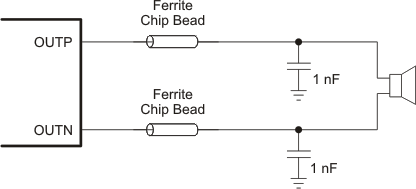
TPA2080D1 ferrite_chip_los520.gifFigure 21. Typical Ferrite Chip Bead Filter

Table 1. Suggested Chip Ferrite Bead

LOAD VENDOR PART NUMBER SIZE
8 Ω Murata BLM18EG121SN1 0603
4 Ω TDK MPZ2012S101A 0805