ZHCSGR2D August 2017 – February 2021 THS4561
PRODUCTION DATA
- 1 特性
- 2 应用
- 3 说明
- 4 Revision History
- 5 Device Comparison Table
- 6 Pin Configuration and Functions
-
7 Specifications
- 7.1 Absolute Maximum Ratings
- 7.2 ESD Ratings
- 7.3 Recommended Operating Conditions
- 7.4 Thermal Information
- 7.5 Electrical Characteristics: VS+ – VS– = 5 V to 12 V
- 7.6 Typical Characteristics: (VS+) – (VS–) = 12 V
- 7.7 Typical Characteristics: (VS+) – (VS–) = 5 V
- 7.8 Typical Characteristics: (VS+) – (VS–) = 3 V
- 7.9 Typical Characteristics: (VS+) – (VS–) = 3-V to 12-V Supply Range
-
8 Parameter Measurement Information
- 8.1 Example Characterization Circuits
- 8.2 Output Interface Circuit for DC-Coupled Differential Testing
- 8.3 Output Common-Mode Measurements
- 8.4 Differential Amplifier Noise Measurements
- 8.5 Balanced Split-Supply Versus Single-Supply Characterization
- 8.6 Simulated Characterization Curves
- 8.7 Terminology and Application Assumptions
- 9 Detailed Description
- 10Application and Implementation
- 11Power Supply Recommendations
- 12Layout
- 13Device and Documentation Support
- 14Mechanical, Packaging, and Orderable Information
封装选项
机械数据 (封装 | 引脚)
散热焊盘机械数据 (封装 | 引脚)
订购信息
3 说明
THS4561 全差分放大器 (FDA) 可在单端源至差分输出之间提供一个简单接口,从而满足精密模数转换器 (ADC) 的需求。THS4561 具有 8Hz 的超低 1/f 电压噪声拐角频率和 130dB 的低总谐波失真 (THD),同时仅消耗 775µA 的静态电流,非常适用于功率敏感的数据采集 (DAQ) 系统,该系统需要使用放大器和 ADC 组合来改善信噪比 (SNR) 及无杂散动态范围 (SFDR),从而提供高性能。
THS4561 具有所需的负电源轨输入,可用于将直流耦合、以接地为中心的源信号连接到单电源差分输入 ADC。低直流误差和温漂项可满足新兴的高速和高分辨率逐次逼近寄存器 (SAR) 和 Δ-Σ ADC 输入要求。2.85V 至 12.6V 电源电压范围、灵活的输出共模设置以及电源余量低等特性,有助于符合多种 ADC 输入和数模转换器 (DAC) 输出的要求。
THS4561 器件的额定工作温度范围是 –40°C 至 +125°C。
器件信息
| 器件型号 | 封装(1) | 封装尺寸(标称值) |
|---|---|---|
| THS4561 | VSSOP (8) | 3.00mm × 3.00mm |
| WQFN (10) | 2.00mm x 2.00mm | |
| VQFN (16) | 3.00mm × 3.00mm |
(1) 如需了解所有可用封装,请参阅数据表末尾的封装选项附录。
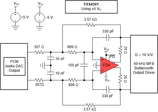
 增益为 10V/V 且具有 50kHz 二阶 MFB 滤波器的 PCM 音频 DAC 输出
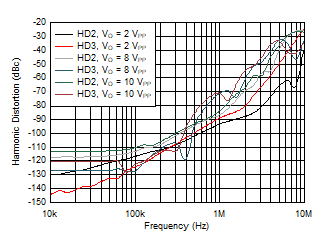
 谐波失真与频率间的关系