ZHCS794B February 2012 – August 2015 SN75DP126
PRODUCTION DATA.
- 1 特性
- 2 应用
- 3 说明
- 4 修订历史记录
- 5 说明 (续)
- 6 Pin Configuration and Functions
-
7 Specifications
- 7.1 Absolute Maximum Ratings
- 7.2 ESD Ratings
- 7.3 Recommended Operating Conditions
- 7.4 Thermal Information
- 7.5 Power Supply Electrical Characteristics
- 7.6 Main Link Input Electrical Characteristics
- 7.7 DisplayPort Main Link Output Electrical Characteristics
- 7.8 HDMI/DVI Main Link Output Electrical Characteristics
- 7.9 HPD/CAD/EN Electrical Characteristics
- 7.10 AUX/DDC/I2C Electrical Characteristics
- 7.11 DisplayPort Main Link Output Switching Characteristics
- 7.12 HDMI/DVI Main Link Switching Characteristics
- 7.13 HPD/CAD Switching Characteristics
- 7.14 AUX/DDC/I2C Switching Characteristics
- 7.15 Typical Characteristics
-
8 Detailed Description
- 8.1 Overview
- 8.2 Functional Block Diagram
- 8.3
Feature Description
- 8.3.1 Implementing the EN Signal
- 8.3.2 Hot Plug Detect (HPD) and Cable Adapter Detect (CAD) Description
- 8.3.3 OVS Function Description
- 8.3.4 AUX and DDC Configuration Details
- 8.3.5 Source-Side Main Link EQ Configuration Details
- 8.3.6 DP-HDMI Adaptor ID Buffer
- 8.3.7 GPU with a Unified AUX/DDC Configuration
- 8.3.8 GPU with Separate DDC and AUX Channels
- 8.4 Device Functional Modes
- 8.5 Register Maps
- 9 Application and Implementation
- 10Power Supply Recommendations
- 11Layout
- 12器件和文档支持
- 13机械、封装和可订购信息
1 特性
- 一个双模 显示端口™(DP++) 输入;可切换至一个 DP++ 输出或者与一个高清多媒体接口 (HDMI) 1.4b 和数字视频接口 (DVI) 兼容的 TMDS 输出
- 支持包括 HBR2 数据速率达到 5.4 Gbps 在内的 DP v1.1a 和 DP v1.2 信令
- 支持线缆长度为 10 米且 TMDS 时钟频率高达 340 MHz 的 HDMI 1.4b
- 到 AMD,英特尔,和 NVIDIA 图形处理器的无粘结逻辑接口
- 通过针对显示端口连接的链路协商的自动配置
- 针对 HDMI/DVI 接收端识别集成的可访问显示数据通道 (DDC) 的 DP-HDMI 适配器 ID
- 针对显示端口和 TMDS 输出的带有可调电压摆幅和预加重增益的输出信号调节
- 高可配置输入变量均衡器
- 两个含针对最低功率的双路电源配置的器件选项
- 2kV 静电放电 (ESD) 人体放电模式 (HBM) 保护
- 温度范围:0°C 至 85°C
- 56 引脚 5mm x 11mm 四方扁平无引线 (QFN) 封装
2 应用
- 笔记本电脑
- 台式计算机
- 计算机扩展坞
- 计算机独立视频卡
3 说明
SN75DP126 将一个双模式显示端口 (DP++) 输入切换至一个双模式显示端口 (DP++) 接收端输出或者一个 HDMI/DVI 接收端输出。HDMI/DVI 输出有一个内置的与 DVI 1.0 和 HDMI 1.4b 标准 TMDS 信令兼容的电平转换器,并且其最大额定数据速率高达 3.4Gbps,从而支持大于 1920 x 1440 的分别率以及 1080p 上的 HDTV 深色功能。当选择 HDMI/DVI 来表示支持 HDMI 信令的时候,可访问一个集成的 DP-HDMI 适配器 ID 缓冲器。
此器件对与 PCB 相关的频率损失和切换相关的损失进行补偿以提供从源到接收端的最优的电气性能。DP++ 主链路信号输入到具有可选择升压设置的功能可配置均衡器。
在 SN75DP126 DP++ 主链路输出上,可提供差分输出电压 (VOD) 摆幅的四个主级和预加重的四个主级以及升压调整的次级,通过 I2C 编程,用于对主链路输出的微调。此器件可监视 AUX 通道并自动调整输出信令电平和基于 DP 链路协商命令的输入均衡器。
器件信息(1)
| 器件型号 | 封装 | 封装尺寸(标称值) |
|---|---|---|
| SN75DP126 | WQFN (56) | 11.00mm x 5.00mm |
- 要了解所有可用封装,请见数据表末尾的可订购产品附录。
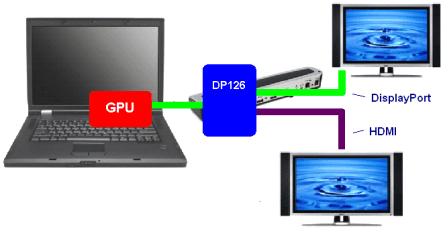
典型应用
