ZHCSDN2 April   2015 LM3632A

PRODUCTION DATA.  

  1. 特性
  2. 应用
  3. 说明
  4. 修订历史记录
  5. Pin Configuration and Functions
  6. Specifications
    1. 6.1 Absolute Maximum Ratings
    2. 6.2 ESD Ratings
    3. 6.3 Recommended Operating Conditions
    4. 6.4 Thermal Information
    5. 6.5 Electrical Characteristics
    6. 6.6 I2C Timing Requirements (SDA, SCL)
    7. 6.7 Typical Characteristics
  7. Detailed Description
    1. 7.1 Overview
    2. 7.2 Functional Block Diagram
    3. 7.3 Features Description
      1. 7.3.1 Backlight
        1. 7.3.1.1 Brightness Control
          1. 7.3.1.1.1 LED Current with PWM Disabled
          2. 7.3.1.1.2 LED Current with PWM Enabled
        2. 7.3.1.2 Sloper
        3. 7.3.1.3 Mapper
        4. 7.3.1.4 PWM Input
        5. 7.3.1.5 PWM Minimum On/Off Time
        6. 7.3.1.6 PWM Resolution and Input Frequency Range
        7. 7.3.1.7 PWM Hysteresis
        8. 7.3.1.8 PWM Timeout
        9. 7.3.1.9 Backlight Boost Converter
          1. 7.3.1.9.1 Headroom Voltage
          2. 7.3.1.9.2 Backlight Protection and Faults
            1. 7.3.1.9.2.1 Overvoltage Protection (OVP) and Open-Load Fault Protection
            2. 7.3.1.9.2.2 Overcurrent Protection (OCP) and Overcurrent Protection Flag
      2. 7.3.2 LCM Bias
        1. 7.3.2.1 Display Bias Boost Converter (VVPOS, VVNEG)
        2. 7.3.2.2 Auto Sequence Mode
        3. 7.3.2.3 Wake-up Mode
        4. 7.3.2.4 Active Discharge
        5. 7.3.2.5 LCM Bias Protection and Faults
          1. 7.3.2.5.1 LCM Overvoltage Protection
          2. 7.3.2.5.2 VNEG Overvoltage Protection
          3. 7.3.2.5.3 VPOS Short Circuit Protection
          4. 7.3.2.5.4 VNEG Short Circuit Protection
      3. 7.3.3 Flash
        1. 7.3.3.1 Flash Boost Converter
        2. 7.3.3.2 Start-Up (Enabling The Device)
        3. 7.3.3.3 Pass Mode
        4. 7.3.3.4 Flash Mode
        5. 7.3.3.5 Torch Mode
        6. 7.3.3.6 Power Amplifier Synchronization (TX)
        7. 7.3.3.7 VIN Monitor
        8. 7.3.3.8 Flash Fault Protections
          1. 7.3.3.8.1 Fault Operation
          2. 7.3.3.8.2 Flash Time-Out
          3. 7.3.3.8.3 Overvoltage Protection (OVP)
          4. 7.3.3.8.4 Current Limit
          5. 7.3.3.8.5 FLED and/or FL_OUT Short Fault
      4. 7.3.4 Software RESET
      5. 7.3.5 EN Input
      6. 7.3.6 Thermal Shutdown (TSD)
    4. 7.4 Device Functional Modes
      1. 7.4.1 Modes of Operation
    5. 7.5 Programming
      1. 7.5.1 I2C-Compatible Serial Bus Interface
        1. 7.5.1.1 Interface Bus Overview
        2. 7.5.1.2 Data Transactions
        3. 7.5.1.3 Acknowledge Cycle
        4. 7.5.1.4 Acknowledge After Every Byte Rule
        5. 7.5.1.5 Addressing Transfer Formats
    6. 7.6 Register Maps
      1. 7.6.1  Revision (Address = 0x01) [reset = 0x05]
      2. 7.6.2  Backlight Configuration1 (Address = 0x02) [reset = 0x30]
      3. 7.6.3  Backlight Configuration2 (Address = 0x03) [reset = 0x0D]
      4. 7.6.4  Backlight Brightness LSB (Address = 0x04) [reset = 0x07]
      5. 7.6.5  Backlight Brightness MSB (Address = 0x05) [reset = 0xFF]
      6. 7.6.6  Flash/Torch Current (Address = 0x06) [reset = 0x3E]
      7. 7.6.7  Flash Configuration (Address = 0x07) [reset = 0x2F]
      8. 7.6.8  VIN Monitor (Address = 0x08) [reset = 0x03]
      9. 7.6.9  I/O Control (Address = 0x09) [reset = 0x00]
      10. 7.6.10 Enable (Address = 0x0A) [reset = 0x00]
      11. 7.6.11 Flags1 (Address = 0x0B) [reset = 0x00]
      12. 7.6.12 Display Bias Configuration (Address = 0x0C) [reset = 0x18]
      13. 7.6.13 LCM Boost Bias (Address = 0x0D) [reset = 0x1E]
      14. 7.6.14 VPOS Bias (Address = 0x0E) [reset = 0x1E]
      15. 7.6.15 VNEG Bias (Address = 0x0F) [reset = 0x1C]
      16. 7.6.16 Flags2 (Address = 0x10) [reset = 0x00]
  8. Application and Implementation
    1. 8.1 Application Information
    2. 8.2 Typical Application
      1. 8.2.1 Design Requirements
      2. 8.2.2 Detailed Design Procedure
        1. 8.2.2.1 External Components
        2. 8.2.2.2 Inductor Selection
        3. 8.2.2.3 Boost Output Capacitor Selection
        4. 8.2.2.4 Input Capacitor Selection
      3. 8.2.3 Application Curves
        1. 8.2.3.1 Backlight Curves
        2. 8.2.3.2 LCM Bias Curves
        3. 8.2.3.3 Flash Curves
  9. Power Supply Recommendations
  10. 10Layout
    1. 10.1 Layout Guidelines
    2. 10.2 Layout Example
  11. 11器件和文档支持
    1. 11.1 器件支持
      1. 11.1.1 第三方产品免责声明
    2. 11.2 文档支持
      1. 11.2.1 相关文档
    3. 11.3 商标
    4. 11.4 静电放电警告
    5. 11.5 术语表
  12. 12机械、封装和可订购信息

封装选项

机械数据 (封装 | 引脚)
散热焊盘机械数据 (封装 | 引脚)
订购信息

1 特性

  • 可驱动多达两个灯串(通常为 8 个串联的 LED)
    • 集成背光升压转换器,最高输出电压达 29V
    • 两个低侧恒流 LED 驱动器,最高输出电流达 25mA
  • 背光效率高达 90%
  • 11 位指数或线性调光
  • 具有外部脉宽调制 (PWM) 输入,可实现内容自适应背光控制 (CABC) 背光操作
  • LCD 偏置电源效率 > 85%
  • 可编程的正 LCD 偏置电源(4V 至 6V),最大输出电流达 50mA
  • 可编程的负 LCD 偏置电源(-6V 至 -4V),最大输出电流达 50mA
  • 1.5A 闪光灯 LED 升压转换器
  • 闪光灯效率 > 85%
  • 输入电压范围:2.7V 至 5V

2 应用

  • 智能手机 LCD 背光照明和偏置电源
  • 小型平板电脑 LCD 背光照明和偏置电源

3 说明

LM3632A 器件集成了用于 LCD 面板背光照明和摄像机闪光灯的白光发光二极管 (WLED) 驱动器以及用于 LCD 面板的偏置电源。 该器件具备 LED 驱动器所需的全套安全功能,并且效率高达 90%,正/负偏置电源轨精度高达 1.5%。 该器件最多能够驱动 16 个背光 LED,是中小型显示屏的理想选择。 该器件可使用由同步升压转换器供电的 1.5A 恒流 LED 驱动器来驱动闪光灯。 高侧闪光灯电流源支持 LED 阴极接地操作。

LM3632A 兼具高集成度和可编程性,无需修改硬件即可适应各类应用。

器件信息(1)

器件型号 封装 封装尺寸(最大值)
LM3632A DSBGA (30) 2.47mm x 2.07mm
  1. 要了解所有可用封装,请见数据表末尾的可订购产品附录。

简化电路原理图

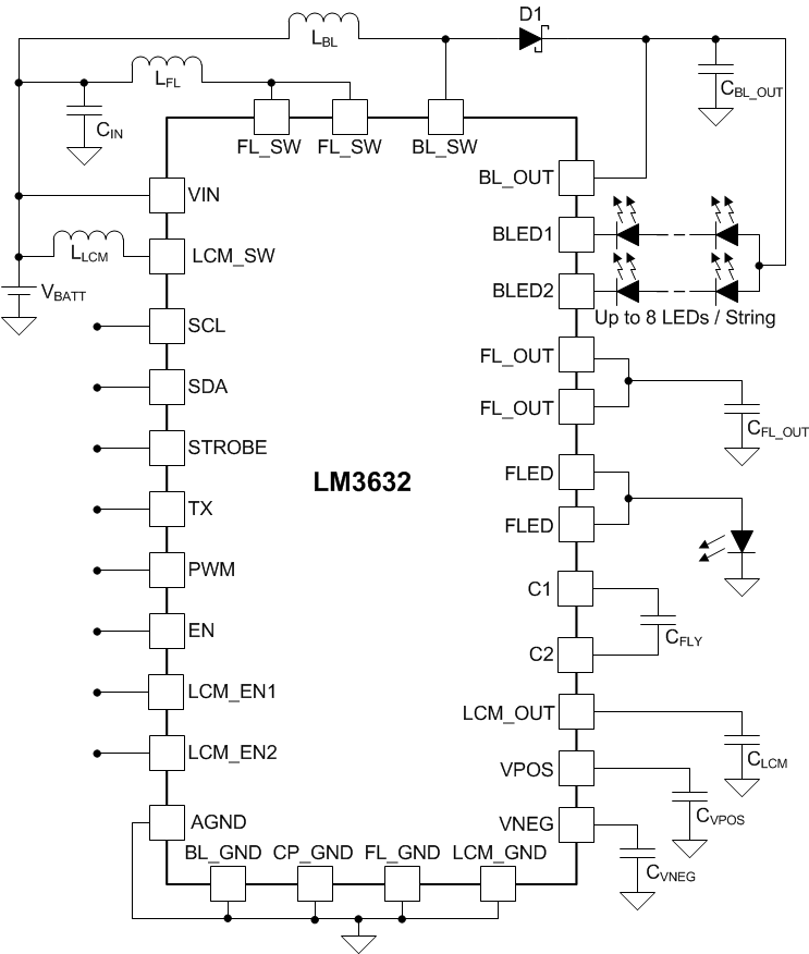
LM3632A LM3632_smpl_sch.gif

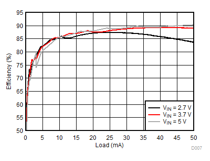
背光效率,2P7S

LM3632A D007_SNVSA63.gif