ZHCSJK1G November 2002 – May 2019 LM2733
PRODUCTION DATA.
- 1 特性
- 2 应用
- 3 说明
- 4 修订历史记录
- 5 Pin Configuration and Functions
- 6 Specifications
- 7 Detailed Description
-
8 Application and Implementation
- 8.1 Application Information
- 8.2
Typical Application
- 8.2.1 Design Requirements
- 8.2.2
Detailed Design Procedure
- 8.2.2.1 Selecting the External Capacitors
- 8.2.2.2 Selecting the Output Capacitor
- 8.2.2.3 Selecting the Input Capacitor
- 8.2.2.4 Feedforward Compensation
- 8.2.2.5 Selecting Diodes
- 8.2.2.6 Setting the Output Voltage
- 8.2.2.7 Switching Frequency
- 8.2.2.8 Duty Cycle
- 8.2.2.9 Inductance Value
- 8.2.2.10 Maximum Switch Current
- 8.2.2.11 Calculating Load Current
- 8.2.2.12 Design Parameters VSW and ISW
- 8.2.2.13 Thermal Considerations
- 8.2.2.14 Minimum Inductance
- 8.2.2.15 Inductor Suppliers
- 8.2.3 Application Curves
- 9 Power Supply Recommendations
- 10Layout
- 11器件和文档支持
- 12机械、封装和可订购信息
8.2.2.11 Calculating Load Current
As shown in the figure which depicts inductor current, the load current is related to the average inductor current by the relation:
Where "DC" is the duty cycle of the application. The switch current can be found by:
Inductor ripple current is dependent on inductance, duty cycle, input voltage and frequency:
combining all terms, we can develop an expression which allows the maximum available load current to be calculated:

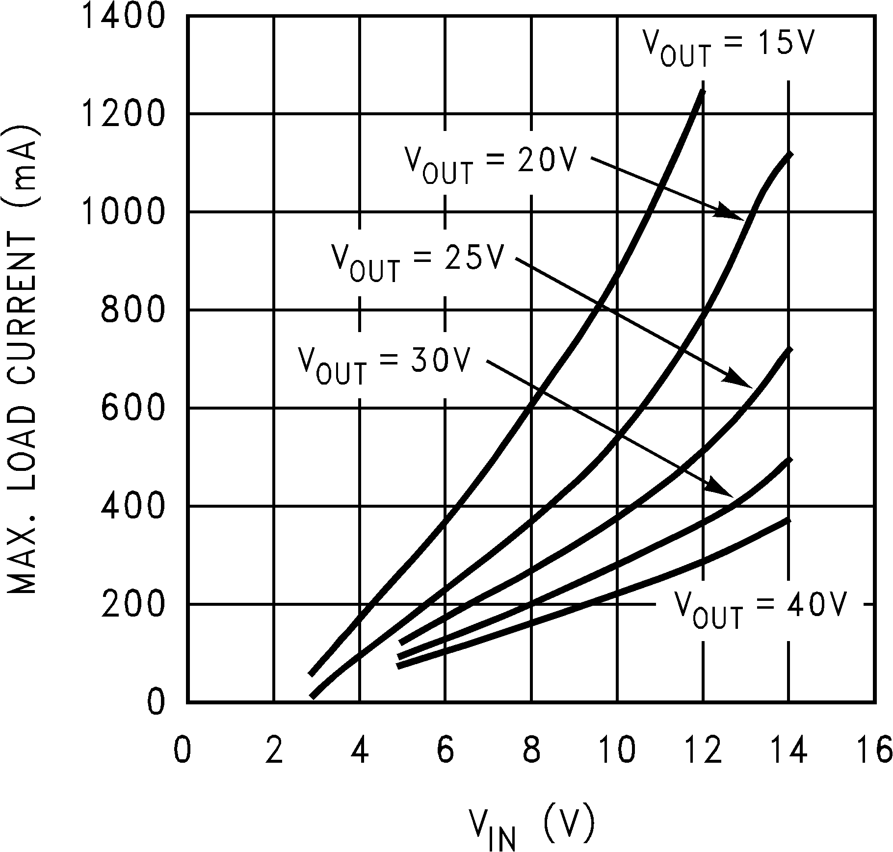
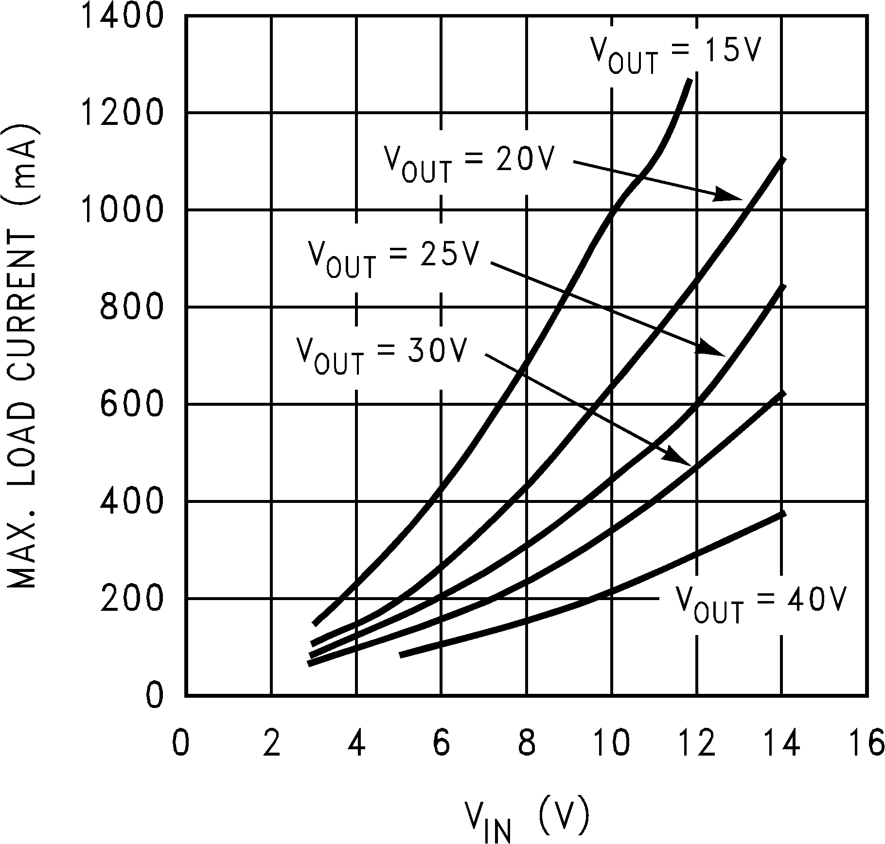
The equation shown to calculate maximum load current takes into account the losses in the inductor or turn-OFF switching losses of the FET and diode. For actual load current in typical applications, we took bench data for various input and output voltages for both the "X" and "Y" versions of the LM2733 device and displayed the maximum load current available for a typical device in graph form:
 Figure 28. Max. Load Current vs VIN - "X"
  Figure 29. Max. Load Current vs VIN - "Y"