ZHCSM23 December 2021 LDC3114
PRODUCTION DATA
- 1 特性
- 2 应用
- 3 说明
- 4 Revision History
- 5 Pin Configuration and Functions
- 6 Specifications
-
7 Detailed Description
- 7.1 Overview
- 7.2 Functional Block Diagram
- 7.3 Feature Description
- 7.4 Device Functional Modes
- 7.5 Register Maps
-
8 Application and Implementation
- 8.1
Application Information
- 8.1.1 Theory of Operation
- 8.1.2 Designing Sensor Parameters
- 8.1.3 Setting COM Pin Capacitor
- 8.1.4 Defining Power-On Timing
- 8.1.5 Configuring Button or Raw Data Scan Rate
- 8.1.6 Programming Button or Raw Data Sampling Window
- 8.1.7 Scaling Frequency Counter Output
- 8.1.8 Setting Button Triggering Threshold
- 8.1.9 Tracking Baseline
- 8.1.10 Mitigating False Button Detections
- 8.1.11 Reporting Interrupts for Button Presses, Raw Data Ready and Error Conditions
- 8.1.12 Estimating Supply Current
- 8.2 Typical Application
- 8.1
Application Information
- 9 Power Supply Recommendations
- 10Layout
- 11Device and Documentation Support
- 12Mechanical, Packaging, and Orderable Information
8.1.12 Estimating Supply Current
When the LDC3114 is active (in either Normal Power Mode or Low Power Mode), use Equation 15 to determine the current:
Equation 15. 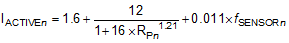
where
- IACTIVEn is the supply current in mA during active sampling
- RPn is the sensor parallel resonant impedance in kΩ
- fSENSORn is the sensor frequency in MHz
- n is the channel index, that is, n = 0, 1, 2, or 3 for LDC3114
The LDC3114 is only actively sampling the enabled channels during a fraction of the scan window. Equation 16 determines the average supply current:
Equation 16. 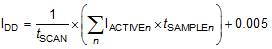
where
- IDD is the average supply current in mA
- tSCAN is the scan window (set by the scan rate) in ms
- IACTIVEn is the supply current when the device is active as defined by Equation 15
- tSAMPLE is the button sampling window in ms